|
You are here: Optimization Module and Tutorial > Optimization of 2D Shape Tutorial > Setting up the model > Defining Physics and Conditions
|
Defining Physics and Conditions
The physics and conditions are specified as follows:
Adding Modules
|
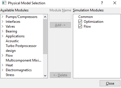
Figure 9.25 - Adding modules |
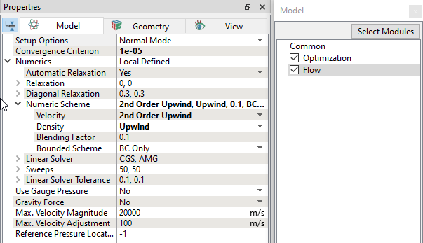
Flow module
|
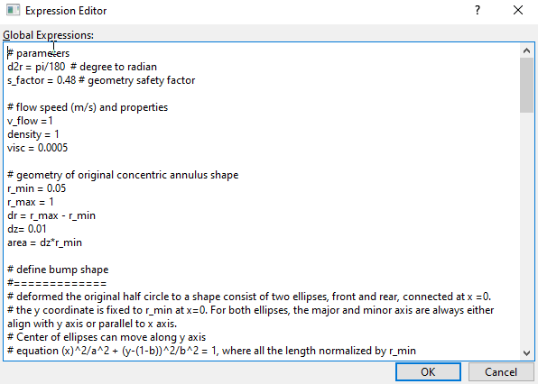
Global Expression for Optimization
# parameters d2r = pi/180 # degree to radian s_factor = 0.48 # geometry safety factor # flow speed (m/s) and properties v_flow =1 density = 1 visc = 0.0005 # geometry of original concentric annulus shape r_min = 0.05 r_max = 1 dr = r_max - r_min dz= 0.01 area = dz*r_min # define bump shape #============= # deformed the original half circle to a shape consist of two ellipses, front and rear, connected at x =0. # the y coordinate is fixed to r_min at x=0. For both ellipses, the major and minor axis are always either align with y axis or parallel to x axis. # Center of ellipses can move along y axis # equation (x)^2/a^2 + (y-(1-b))^2/b^2 = 1, where all the length normalized by r_min # use length (multiplier of r_min) and tip angle iith y-axis (in degree) at x = 0 to define the ellipses shape fl = optimization.fl rl = optimization.rl ftheta_new = optimization.fang rtheta_new = optimization.rang # validate input: theta>arctan(2/l) ftheta_min = atan(2.1/fl)/d2r rtheta_min = atan(2.1/rl)/d2r ct1 = ftheta_new-ftheta_min ct2 = rtheta_new-rtheta_min ftheta = (ftheta_new>ftheta_min)? ftheta_new : ftheta_min rtheta = (rtheta_new>rtheta_min)? rtheta_new : rtheta_min # slope dx/dy = -cot (angle) fs = -cot(ftheta*d2r) rs = -cot(rtheta*d2r) # solve for a, and b for both front and rear ellipses fb = (fl+fs)/(fl+2*fs) rb = (rl+rs)/(rl+2*rs) fa = sqrt(fb^2*fl^2/(2*fb-1)) ra = sqrt(rb^2*rl^2/(2*rb-1)) # define front (upstream) ellipse for y<=0, flx = fa*r_min fly = fb*r_min # define rear (downstream) ellipse for y>=0 rlx = ra*r_min rly = rb*r_min # move coordiates of mesh #================= # define a radial vector start from origin, and go through current point # the vector is defined as x=(xp/rp)r, y=(yp/rp)r xp = x yp = y rp = sqrt(xp^2+yp^2) ff = xp/rp gg=y/rp # Radius ratio in original mesh r_ratio = (r_max-rp)/dr # find intersection points of the radial vector with both front/back ellipses, still solving equation normalized by r_min # intersection with front FA = fb^2*ff^2+fa^2*gg^2 FB = 2*gg*fa^2*(fb-1) FC = fa^2*(1-2*fb) # r> 0, so only use positive r results, also convert to real size fr_min = ((-FB + sqrt(FB^2-4*FA*FC))/(2*FA))*r_min # intersection with rear RA = rb^2*ff^2+ra^2*gg^2 RB = 2*gg*ra^2*(rb-1) RC = ra^2*(1-2*rb) # r> 0, so only use positive r results, also convert to real size rr_min = ((-RB + sqrt(RB^2-4*RA*RC))/(2*RA))*r_min # new r rn = (xp>0)? r_max - r_ratio*(r_max - fr_min) : r_max - r_ratio*(r_max-rr_min) xnew = x*rn/rp ynew = y*rn/rp znew = z # output section # ========= # output total force drag = -(flow.px@cylinder_min + flow.tx@cylinder_min) plot.drag = drag #plot.drag: Drag Force [N] # drag coefficient cd = 2*drag/(density*v_flow^2*area) plot.cd = cd #plot.cd: CD [] # Reynolds Number Re = density*v_flow*2*r_min/visc plot.Re = Re #plot.Re: Reynolds Number []
|
Optimization module
|
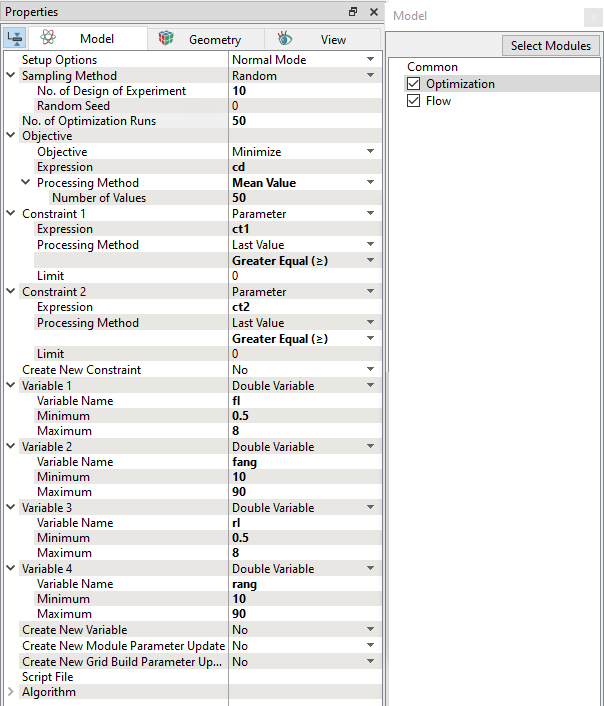
Figure 9.28 - Optimization module parameters |
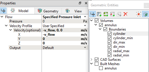
Boundary conditions
The boundary conditions are specified as follows:
Symmetry
|
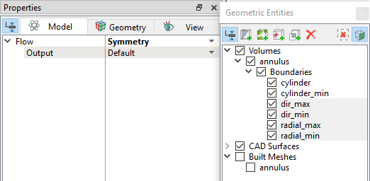
Figure 9.30 - Symmetry Boundary conditions |
Fluid properties
|
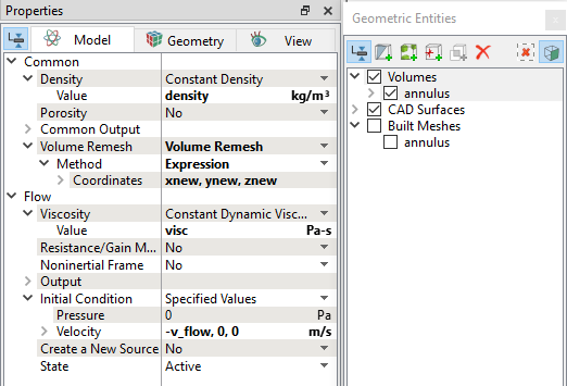
Figure 9.31 - Fluid properties |
Volume Remeshing
|
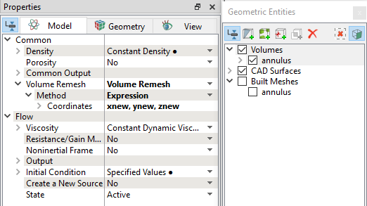
Figure 9.32 - Volume Remeshing |