Translation
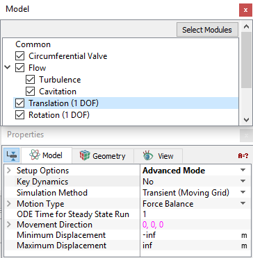
Translation (1 DOF) is used to dictate the linear motion of boundaries and volumes, either explicitly or in terms of a dynamic force balance. The translational motion is available only in one direction. Any number of Translation (1 DOF) modules can be added, each with its own dynamics, but they need to be given a different Module Name.
|
The parameters under Translation (1 DOF) can be specified as follows:
The following conditions and parameters are available in the Properties Panel:
|
Figure 5.269 - Dynamics - Translation options |
|
Note: The template, if used should be in Extended Mode to view all the parameters. |
Setup Options
|
This applies to the display of settings/parameters and can be switched back and forth without resetting any parameter. Setup Options offers two modes for the setup of a model:
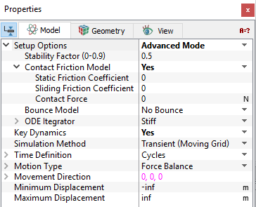
When the Advanced Mode is selected from the Setup Options drop-down list, the following settings appear in the Properties Panel:
|
Key Dynamics
Key dynamics for a selected Dynamics module may be set to No or Yes. Yes, means that module will control the Time Definition for all modules.
|
Note: Only one module among Translation (1 DOF)/ Rotation (1 DOF) may be designated as Key Dynamics = Yes. Setting Key Dynamics = Yes for a second Module will reset the first module’s Key Dynamics to No. |
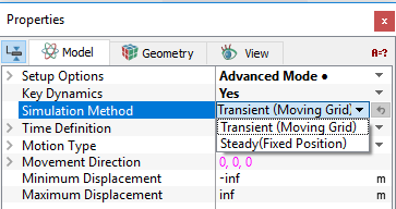
Simulation Method
|
The two methods of simulation available under Simulation Method are:
|
Figure 5.273 - Simulation method options |
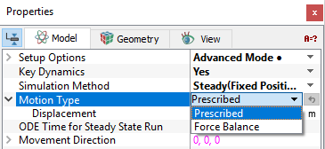
Motion Type
The motion for a selected Volume/Boundary is specified as follows: (see Figure 5.274)
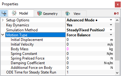
- Force Balance: The valve position is obtained by solving ODE following the transient time step. The Force Balance parameters for the Translation (1 DOF) include (see Figure 5.275):
- Initial Displacement
- Initial Velocity: Allows to introduce an initial velocity (t=0) for a moving Volume/Boundary. This is applied at the start of the simulation (t=0). The unit for Initial Velocity is m/s. A positive value of the Initial Velocity is in the same direction as the direction of movement vector.
- Body Mass
- Spring Constant
- Spring Preload Force
- Damping Coefficient: Generates a force opposite to the velocity and depends on the average value defined by the user. The force associated with the damping coefficient opposes the direction of motion.
- Additional Force on Body: Allows the user to add a force to the force balance for Translation (1 DOF) motion. This option is relevant and displayed when Advanced Mode is selected. This is applied in the direction of the Movement Direction vector.
- Prescribed: Volume/Boundary will move directly to prescribed position at the first time-step. The Displacement is specified here. Having selected the Prescribed option, the user typically provides an expression for the displacement as a function of time using the Expression Editor. This specified Displacement and associated velocity can be accessed via the Expression Variables: trans_1d.displacement and trans_1d.velocity. The unit for Displacement is m.
- When a constant displacement is specified for a Transient (Moving Grid) simulation, the Volume/Boundary will move directly to that position at the first time-step.
- When Steady (Fixed Position) is used with the Prescribed option, the Volume/Boundary will move directly to the displacement position corresponding to t=0.
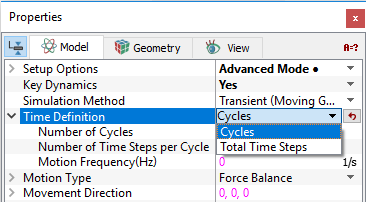
Time Definition
|
This determines the number and size of time-steps for a transient simulation based on: Cycles and Total Time Steps. This option is relevant and displayed only for Transient (Moving Grid). This option is enabled for a selected module when the corresponding Key Dynamics option is set to Yes. The Time Definition options are:
|
Figure 5.276 - Time Definition options |
ODE Time for Steady-state Run
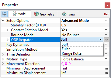
The default value for the General.ODE Time for Steady-State Run is 1. A smaller value implies a smaller pseudo time-step, resulting in a slower, but more stable solution. This option is enabled for a selected module when the corresponding Key Dynamics option is set to No.
Movement Direction
This is used to specify the direction of the positive motion for a translating Volume/Boundary. This is specified in terms of  components relative to the model coordinate system.
|
Note: For the Valve Template Mesher available in Simerics-MP, the Movement Direction should be selected to correspond with the opening direction of the valve. |
Minimum Displacement
This limits the minimum value of displacement specified by the Translation (1 DOF) module. The unit for Minimum Displacement is m. It can be thought of as a physical limitation or stop.
When the displacement (trans_1d[.subname].displacement) corresponding to Prescribed or Force Balance reaches the Minimum Displacement:
- The value of trans_1d[.subname].displacement will not decrease below that point.
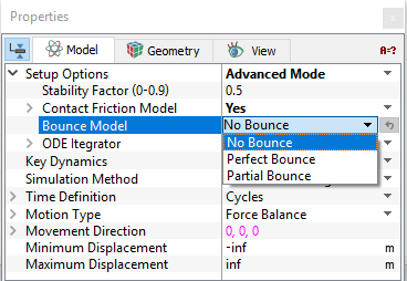
- The volume/boundary bounces back with an energy corresponding to the selected Bounce Model.
|
Note: The default value of -1.#INF means there is no physical limitation to the object’s motion opposite to the Movement Direction, i.e. trans_1d.displacement can go to “negative infinity.” |
Maximum Displacement
This limits the maximum value of displacement specified by the Translation (1 DOF) module. The unit for Maximum Displacement is m. It can be thought of as a physical limitation or stop.
When the displacement (trans_1d[.subname].displacement) corresponding to Prescribed or Force Balance reaches the Maximum Displacement:
-
The value of trans_1d[.subname].displacement will not increase beyond that point.
-
The volume/boundary bounces back with an energy corresponding to the selected Bounce Model.
|
Note: The default value of 1.#INF means there is no physical limitation to the object’s motion in the Movement Direction, i.e. trans_1d.displacement can go to “positive infinity.” |