Boundary Conditions
|
The boundary conditions and related Multiphase parameters are specified as follows: |
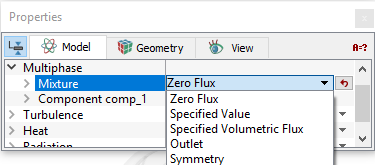
Zero Flux
|
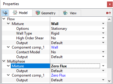
This condition means that there is no flux or gradient of components normal to the boundary. This boundary condition typically corresponds to a solid boundary in the model.
Contact Model The Contact Angle allows to set the wetting angle for a Component at a Wall. The Contact Model is activated to Yes for a component under the Flow module and the Angle is specified. |
Figure 5.108 - Zero flux |
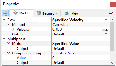
Specified Value
|
This condition allows to set the volume fractions of the components at an opening.
|
Figure 5.109 - Specified values |
|
Note: The sum of the volume fractions for all components at a boundary should add to one. If the sum of the volume fractions for all components at a boundary is not equal to one, the program will give an error message when the simulation is started. |
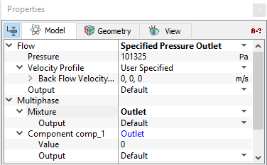
Outlet
|
This condition allows to set the volume fractions of the components at an opening.
The volume fractions specified for the components at an Outlet boundary should be set to the volume fraction that would enter in the event of back flow. The volume fraction set at an outlet does not dictate the mass fraction that exits the boundary. The volume fraction of the component for any fluid exiting the domain is based on the internal (upwind) volume fraction. |
Figure 5.110 - Outlet |
|
Note: The sum of the volume fractions for all components at a boundary should be one. If the sum of the volume fractions for all components at a boundary do not add to one, the program will give an error message when the simulation is started. |
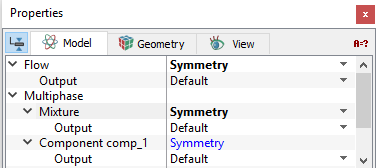
Symmetry
|
This condition means that there is no shear, no normal component of velocity and no normal gradient of pressure at the boundary. This boundary condition usually corresponds to a physical symmetry in the model.
|
Figure 5.111 - Symmetry |
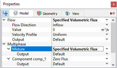
Specified Volumetric Flux
|
This allows to set the volumetric flux of each component at an opening. This corresponds to the Volumetric Flow boundary condition for the Flow module. For the Specified Volumetric Flux Boundary Condition, the Value of the volume fraction for each component needs to be set under Component > Specified Value. |
Figure 5.112 - Specified volumetric flux |
Interface Conditions
The Interface parameters for the Multiphase module are similar to those for the Boundaries, if and only if the State of the volume on one side of the interface has been set to Blanked under the Flow menu in the Properties Panel. If instead, the volume is set to Blanked or Active Multi-component Flow on both sides of an interface, then it can only be assigned as a Default Interface.