中文 English
You are here: Automotive Templates and Tutorials > Vehicle Template > Vehicle FEAF Tutorial > Defining Physics and Conditions

Defining Physics and Conditions

The physics and conditions are specified as follows:

Modules
  1. Select Model Panel.
  2. Vehicle, Flow and Turbulence are automatically added to the Model Panel by the Vehicle Template Mesher.
 

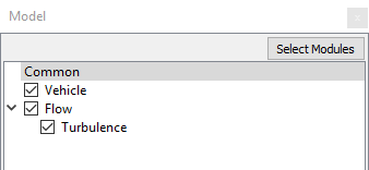
Figure 7.50 - Modules

Operating Parameters
  1. Select Vehicle in the Model Panel.
  2. Select Extended Mode from the Setup Options drop-down list in the Model Tab of Properties Panel.
  3. Select Front End Air Flow from the Analysis Options drop-down list in the Model Tab of Properties Panel.

  4. Enter 12.5 m/s for Wind Speed.


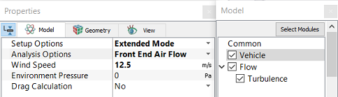
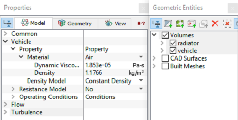
Figure 7.51 - Vehicle template parameters

Boundary Conditions

The boundary conditions for the simulation are automatically set by the Vehicle template.

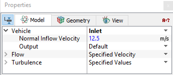
Figure 7.52 - Inlet conditions


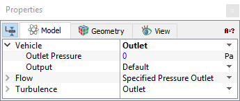
Figure 7.53 - Outlet conditions


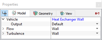
Figure 7.54 - Heat exchanger conditions
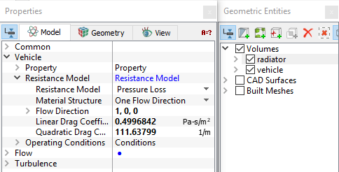
Fluid properties
  1. Select all Volumes in the Geometric Entities Panel.
  2. Select Model Tab in the Properties Panel.
  3. Enter the parameters for Property list under Vehicle as follows.
  • Material: Air
  • Dynamic Viscosity1.853e-05 Pa-s
  • Density: 1.1766 kg/m3


Figure 7.55 - Fluid properties

Resistance Model
  1. Select Radiator under Volumes the Geometric Entities Panel.
  2. Select Model Tab in the Properties Panel.
  3. Enter the following parameters for Resistance Model list under Vehicle as follows.
  • Resistance Model: Pressure Loss
  • Material StructureOne flow direction
  • Flow Direction: 1, 0, 0
  • Linear Drag Coefficient: 0.4996842 Pa-s/m2
  • Quadratic Drag Coefficient: 111.63799 1/m


Figure 7.56 - Resistance model

´ Note: For calculation of Linear Drag Coefficient and Quadratic Drag Coefficient, refer template.


Copyright © 2023 Simerics Inc.,