Conditions
This section explains the conditions related to the Boundaries and Volumes in a translational valve simulation.
The boundary conditions for a desired boundary can be specified through:
Geometric Entities Panel > Boundaries > [Desired boundary]
Properties Panel > Model Tab > respective valve (Spool Valve) > [Desired options]
The Translational Valve template has following boundary conditions.
![]()
Figure 6.521 - Valve - Conditions
-
Cylinder Surfaces: This corresponds to the boundaries along which the valve slides during its motion. This boundary does not necessarily have to be cylindrical in shape. It is necessary that the projection of this surface on the plane perpendicular to the valve movement direction (opening direction) should be a single two-dimensional curve. If this boundary condition is associated with a moving wall, then the velocity of the wall should be set in the Flow module and it should be explicitly linked to the Dynamic module using the boundary condition, as shown in the figures below:
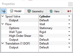
Figure 6.522 - Stationary cylinder
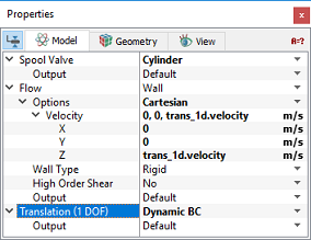
Figure 6.523 - Moving cylinder
Note: The Setup Options should be set to Extended Mode under the valve module to set any boundary condition independently.
- Valve Surfaces: This corresponds to all the moving surfaces. If any of the surfaces of the valve boundary are not normal to the direction of translation (Opening Direction), then velocity of the wall should be set in the Flow module to account for the shear effect on the flow.
Note: The default settings in each module under the template can be accessed and modified, by using the Extended Mode.
-
Valve End Surfaces: This corresponds to the end boundaries of a valve chamber.
Note: The Cylinder Surfaces, Valve Surfaces and Valve End Surfaces are the boundary conditions that are set automatically while meshing using the valve template.
- Inlet: This specifies the inlet flow boundary. A Specified Pressure Inlet is the default boundary condition in the Flow module for a valve inlet boundary.
Note: Inlet boundary cannot be a part of a valve chamber. If a boundary functions as both an inlet and a boundary of the valve chamber. It should be assigned the valve function and subsequently set as an Inlet under the Flow module using Extended Mode.
- Outlet: This specifies the outlet boundary. A Specified Pressure Outlet is the default boundary condition in the Flow module for a valve outlet boundary.
Note: Outlet boundary cannot be a part of a valve chamber. If a boundary functions as both an outlet and a boundary of the valve chamber, it should be assigned the valve function and subsequently set as an outlet under the Flow module using Extended Mode.
- Wall: This specifies a wall boundary. This should only be used if that boundary is not part of the valve chamber. If a boundary functions as both a Wall and a boundary of the valve chamber, that boundary should be assigned the valve function. The module sets the Wall as a default boundary condition for the Flow module with the Default (no connection ) boundary condition for the Dynamics module.
If a wall of a volume outside the valve chamber is associated with a moving valve surface (e.g. via MGI) it should be set as a wall in the valve module as shown in the Figure 6.525 for a leakage gap surrounding the spool valve. Since the inner wall of the leakage gap is in contact with the moving wall (valve), shear effect is accounted by specifying the velocity of the wall in the Flow module and linking it to Dynamics module using dynamic boundary condition as shown.
|
Figure 6.524 - Valve Boundary Surfaces |
|
|
Note: The default values in each module under the template can be accessed and modified, by using the Extended Mode. |
|
The valve template has the following parameters that are assigned to the fluid volumes. The conditions for a desired volume are accessed as follows: Geometric Entities Panel > Volumes > [Desired Volume] Properties Panel > Model Tab > Valve > [Desired options]. The template has additional conditions which apply to Volumes in the simulation under valve module. Each volume may be assigned specific independent volume conditions.
|
Output
Primary and derived variables can be integrated over a selected boundary and stored in the ASCII format file filename_integrals.txt for subsequent Post-Processing. These data can also be displayed real-time in the GUI using the X-Y Plots feature.
The desired output can be activated for a selected boundary in the Model Tab of the Properties Panel. The outputs which can be activated are specified as User Select (Area, Normal). The valve related output variables are available under the Translation (1 DOF) module.
When monitoring Points are created as part of the simulation, the output quantities are stored in the ASCII format file filename_points.txt for subsequent post-processing.