Vane chamber meshing
This section explains the settings for the vane chamber mesh generated using the Rotor Template Mesher. This involves selection of the surfaces, directional characteristics of the mesh and other advanced mesh settings.
The parameters related to Vane meshing can be accessed by setting the Setup Options to Advanced Mode, as shown in Figure 6.195.

Figure 6.195 - Vane template mesher
Rotor
This is used to assign the rotor of the vane pump as follows:
- Select the rotor surface under CAD Surfaces in the Geometric Entities Panel.
- Click Add Surfaces
 icon to the right of Rotor, or click Select Rotor in the Properties Panel.
The selected CAD Surfaces corresponding to the rotor do not have to be cylindrical. If the selected CAD Surfaces are within 1% of the ideal cylinder defined by the parameters Rotor Center, Rotational Axis Vector, and Rotor Radius, the selected rotor will be adjusted to be perfectly cylindrical.
|
Note: Identification of the vanes is not needed for grid generation because the vanes are generated by extrusion of the points where they attach to the rotors. |
Chamber Wall
This is used to assign the chamber wall of the vane pump as follows:
- Select the chamber wall surface under CAD Surfaces in the Geometric Entities Panel.
- Click Add Surfaces icon to the right of Chamber Wall, or click Select Chamber Wall in the Properties Panel.
The selected CAD Surface corresponding to the Chamber Wall does not have to be cylindrical. If the selected CAD Surface is within 1% of the ideal cylinder defined by the parameters Chamber Center, Rotational Axis Vector, and Chamber Radius, the selected Chamber Wall will be adjusted to be perfectly cylindrical.
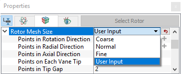
Rotor Mesh SizeThis allows to control the resolution of the mesh created in the vane pumping chamber as:
|

|
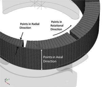
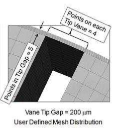
The control parameters associated with User Input (see Figure 6.196) are:
|
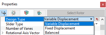
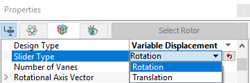
Design TypeThe configuration of the pump is specified by the Design Type option as (see, Figure 6.200):
Translation: This parameter is selected to enable the simulation of a Variable Displacement pump for which the chamber wall translates, thereby changing the pump’s eccentricity and the resulting displacement (see Figure 6.202). Rotation: This parameter is selected to enable the simulation of a Variable Displacement pump for which the chamber wall rotates, thereby changing the pump’s eccentricity and the resulting displacement (see, Figure 6.203).
|


Physical Parameters of the Vane Pump
The physical parameters of the vane pump that govern the working of the vane pump are described below as follows:

Figure 6.204 - Vane pump physical parameters
Number of Vanes
This parameter corresponds to the number of vanes in the pump and it is typically specified during the meshing operation, but it is not required for meshing. Its primary function is to control the time-steps in the template module
The Number of Vanes has no effect on the geometry but this parameter is used in conjunction with the Time Steps Per Vane Rotation to determine the number of degrees the vanes are rotated every time-step.

|
|

|
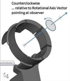
Rotational Axis VectorThe direction of the axis of rotation of the rotor in the laboratory reference frame, specified in coordinates.
|
Rotor Center
This parameter is used in conjunction with the Rotational Axis Vector and Rotor Radius in the Vane Pump Template to generate the mesh and during simulation. This must be set very precisely if tight tolerances (e.g. Tip Clearances) are to be modelled (see, Figure 6.204).
The Rotor Center input can be used in combination with the Rotational Axis Vector and Rotor Radius to perfect a circular Rotor boundary. If the CAD Surface is within 1% of the cylinder defined by the above parameters, the points on the rotor boundary created during the meshing operation are adjusted to precisely conform to the cylinder.
- If the cylindrical boundary generated using the Rotor Radius, Rotational Axis Vector and Rotor Center above does not match the corresponding CAD Surface to within 1% of the radius (as in the case of an elliptical housing), the shape of the CAD Surface is used instead.
- If the above parameters qualify for perfection of the rotor during meshing, this modification applied directly to the rotor boundary and stored in the .sgrd.
Chamber Center
This parameter is used in conjunction with Rotational Axis Vector and Chamber Radius to perfect a circular Chamber Wall. If the CAD Surface is within 1% of the cylinder defined by the above parameters, the points on the Chamber Wall boundary created during the meshing operation are adjusted to precisely conform to the cylinder (see Figure 6.204). Specify the Chamber Center in  coordinates option under Rotor Type.
- If the cylindrical boundary generated using the Chamber Radius, Rotational Axis Vector and Chamber Center above do not match the corresponding CAD Surface to within 1% of the radius (as in the case of an elliptical housing), the shape of the CAD Surface is used instead.
- If the above parameters qualify for perfection of the Chamber Wall during meshing, this modification is applied directly to the chamber wall boundary and is stored in the .sgrd file.
|
Note: Chamber Center is offered as a Vane Mesher Parameter when the Design Type is Variable Displacement or Fixed Displacement. For Balanced, the Chamber Center is computed based on the Chamber Wall’s CAD Surface. |
Pin Center
This parameter is a meshing parameter only available when the Design Type is Variable Displacement with Rotation. It is the rotational center of the Chamber Wall
Specify the Pin Center in  coordinates option under Rotor Type. If specified during the meshing operation, it is passed over to the Pin Center parameter under the Pump Configuration in the Vane Module (see, Figure 6.203).
Slider Rotation: This represents the angle (in degrees) by which the Chamber Wall rotates about the Pin Center for a rotating Variable Displacement pump (see, Figure 6.203).
Slider Displacement: This represents the displacement (in meters) by which the Chamber Wall translates for a translating Variable Displacement pump (see, Figure 6.202).
Sliding Direction: This represents the direction in which the Chamber Wall translates for a translating Variable Displacement pump (see, Figure 6.202).
|
Note: After creation of the numerical mesh, the Vane Angle can still be modified before or during a simulation using the Vane Angle option in the Model Tab, after selecting the Vane module in the Model Panel. The slant of the blades (positive vs. negative) is based on the right-hand rule relative to the Rotational Axis Vector. |
|
Note: The Vane Tip Gap shown under the Pump Configuration in the Model Tab of the Properties Panel and under Rotor Type in the Geometry Tab of the Properties Panel are not linked and can have different values. |
|
Note: If a zero value of the Vane Tip Gap is specified during the Rotor Template Mesher operation, no mesh is included in tip clearance and cannot be adjusted during operation. |
Rotor Radius
This is an optional parameter that can be used in conjunction with the Rotational Axis Vector and the Rotor Center to generate the circular inner boundary of the mesh created inside the vane pump chamber. Specify the radius of the rotor in terms of a positive real number during the Rotor Template Mesher operation in the Geometry Tab of Properties Panel
If the CAD Surface is within 1% of the cylinder defined by the above parameters, the points on the rotor boundary created during the meshing operation are adjusted to precisely conform to the cylinder.
- If the cylindrical boundary generated using the Rotor Radius, Rotational Axis Vector and Rotor Center above does not match the corresponding CAD Surface to within 1% of the radius (as in the case of an elliptical housing), the shape of the CAD Surface is used instead.
- If the above parameters qualify for perfection of the Rotor during meshing, this modification is applied directly to the Rotor boundary and is stored in the .sgrd file.
Chamber Radius
This specifies the radius of the chamber in terms of a positive real number in the Chamber Radius option under the Rotor Type. This input under the Rotor Template Mesher can be used in combination with Rotational Axis Vector and Chamber Center to perfect a circular Chamber Wall. If the CAD Surface is within 1% of the cylinder defined by the above parameters, the points on the Chamber Wall boundary created during the meshing operation are adjusted to precisely conform to the cylinder.
- If the cylindrical boundary generated using the Chamber Radius, Rotational Axis Vector and Chamber Center above does not match the corresponding CAD Surface to within 1% of the radius (as in the case of an elliptical housing), the shape of the CAD Surface is used instead.
- If the above parameters qualify for perfection of the Chamber Wall during meshing, this modification is applied directly to the Chamber Wall boundary and is stored in the .sgrd file.
Curved Rotor in Axial Direction
Specify this option as Yes or No. The two possibilities of this option are:
- Setting this option to Yes will create the rotor volume inner surface mesh for the rotor hub that coheres to the CAD Surface curvature. This enables modelling hubs that have curvature or angles in the axial direction.
- Setting this option to No will create a straight hub whether the corresponding hub mesh is curved or straight.
|
Note: Curved Rotor in Axial Direction should only be used if the hub is curved or angled along the axial direction. |
Keep Tip Profile
Specify this option as Yes or No. This option is typically specified during the meshing operation and automatically copied over to the Vane Template model menu parameters.
If Yes is selected for Keep Tip Profile, select an appropriate CAD Surface or Boundary which is used for the Vane Tip surface shape and remains unchanged during the motion of the Vanes.
|
Note: Keep Tip Profile is only available in Extended Mode and is activated or deactivated in the Geometry Tab of the Properties Panel. |