Rotational
|
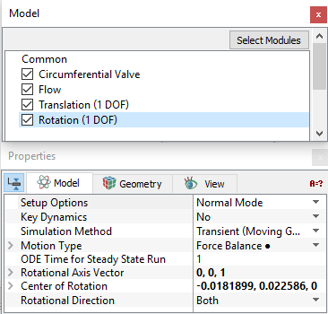
Rotation (1 DOF) is used to dictate the rotational motion of boundaries and volumes, either explicitly or in terms of a dynamic force balance. The rotational motion is available only in one direction. Any number of Rotation (1 DOF) modules can be added, each with its own dynamics, but they need to be given a different Module Name. The parameters under Rotation (1 DOF) can be specified as follows:
The following conditions and parameters are available in the Properties Panel:
|
Figure 5.277 - Dynamics - Rotational options |
|
Note: The template, if used should be in Extended Mode to view all the parameters. |
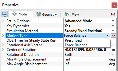
When the Advanced Mode is selected from Setup Options drop-down list, the following settings appear in the Properties Panel:
Motion Type
This dictate whether the motion for a selected Volume/Boundary is Prescribed explicitly or based on a Force Balance. The magnitude of the angle of rotation for the Rotation (1 DOF) are based on the Rotational Axis Vector and the right-hand rule, such that if the axis is pointing at an observer, the angle is increasing in the counterclockwise direction. The motion for a selected Volume/Boundary can be specified as follows: (see Figure 5.278)
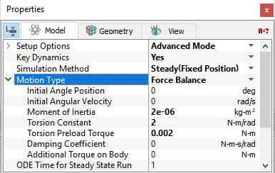
- Force Balance: Enables calculation of the Rotation (1 DOF) dynamics of a volume or boundary as part of the solution. The Force Balance parameters for the Rotation (1 DOF) include (see Figure 5.279):
- Initial Angle Position: Sets the starting angle at time, t=0 for a Volume/Boundary. It is independent of the reference theta used to define the Torsion Preload Torque and Torsion Constant. The unit for Initial Angle Position is deg, while the other variables in the Force Balance equation are in rad, or rad/s.
- Initial Angular Velocity: Sets the rotational velocity (rad/s) at time, t=0 for a Volume/Boundary. The unit for Angular Velocity is rad/s.
- Moment of Inertia: Tendency of a body to resist angular acceleration. The unit for Moment of Inertia is (kg-m2).
- Torsion Constant: Opposes an increase in angle.
- Torsion Preload Torque: This is based on the position of the associated Volume/Boundary during model set-up and does not depend on the value of the Initial Angle Position. It opposes an increase in angle.
- Damping Coefficient: The Rotation (1 DOF) module generates a torque opposite to the angular velocity according to the Force Balance. The retarding torque due to damping depends on the rotational velocity and the user defined Damping Coefficient. The torque associated with the Damping Coefficient opposes the direction of motion.
- Additional Torque on Body: Allows the user to add a source of torque to the Force Balance for Rotation (1 DOF) motion. This is relevant and displayed when Advanced Mode is selected. The angle and torque is based on the Rotational Axis Vector and the right-hand rule, such that if the axis is pointing at an observer, the angle is increasing in the counterclockwise direction. This torque gets added to the Force Balance for Rotation (1 DOF).
- Prescribed: Allows to explicitly dictate the rotation of a Volume/Boundary as a function of time. The Angle Displacement is specified here. The specified Angle Displacement and the associated Angular Velocity can be accessed via the Expression Variables: rotate_1d.angle and rotate_1d.omega to move a Volume/Boundary. The unit for Angle Displacement is deg (not rad).
- If a constant Angle Displacement is specified for a Transient (Moving Grid) simulation, the Volume/Boundary will move directly to that angle at the first time-step.
- If Steady (Fixed Position) simulation is used with the Prescribed option, the Volume/Boundary will move directly to Angle Displacement corresponding to t=0.
Minimum Angle Displacement
This limits the minimum value of angle displacement specified by the Rotation (1 DOF). It is typically used in conjunction with the Volume remesh under Common module to limit the minimum degree of rotation of an associated Volume/Boundary. The unit for Minimum Angle Displacement is deg. It can be thought of as a physical limitation or stop.
When the angle displacement (rotate_1d[.subname].angle) corresponding to Prescribed or Force Balance reaches the Minimum Angle Displacement:
- The value of rotate_1d[.subname].angle will not decrease below that point.
- The volume/boundary bounces back with an energy corresponding to the selected Bounce Model.
|
Note: The default value of -1.#INF means there is no physical limitation to the object’s motion rotation in the negative direction, i.e. rotate_1d.angle can go to “negative infinity.” |
Maximum Angle Displacement
This limits the maximum value of angle displacement specified by the Rotation (1 DOF). It is typically used in conjunction with the Volume remesh under Common module to limit the maximum degree of rotation of an associated Volume/Boundary. The unit for Maximum Angle Displacement is deg. It can be thought of as a physical limitation or stop.
When the angle displacement (rotate_1d[.subname].angle) corresponding to Prescribed or Force Balance reaches the Maximum Angle Displacement:
-
The value of rotate_1d[.subname].angle will not increase beyond that point.
-
The volume/boundary bounces back with an energy corresponding to the selected Bounce Model.
|
Note: The default value of 1.#INF means there is no physical limitation to object’s motion rotation in the positive direction, i.e. rotate_1d.angle can go to “positive infinity.” |