|
You are here: Optimization Module and Tutorial > Optimization of 2D Shape Tutorial > Setting up the model > Building the Mesh
|
Building the Mesh
This section describes the step-by-step procedure to prepare the mesh for the optimization model.
The Template Mesher is used to create the initial mesh and then it is deformed through Volume Remesh. Volume is re-meshed based on the shape of the 2D profile through expressions.
Annulus mesh
|
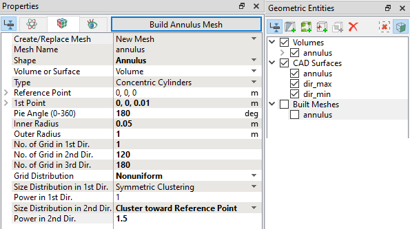
Figure 9.18 - Annulus mesh settings
|
| ´ | Note: The mesh can be edited/replaced by selecting it under Built Meshes, and modify the mesh parameters in the Properties Panel. Click Create Mesh to reflect the changes. |
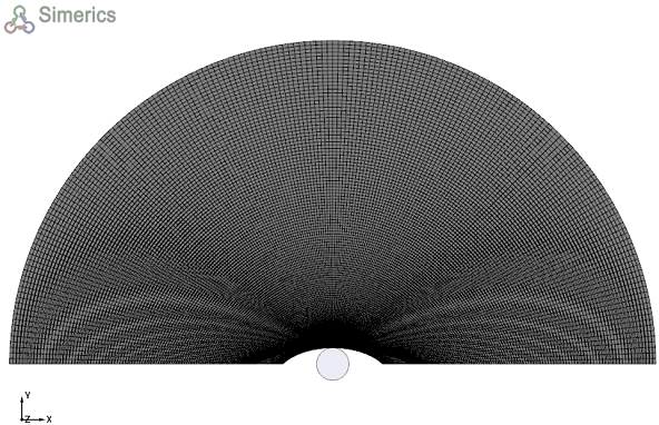
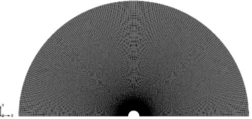
The mesh created for the external flow domain around the 2D shape is shown below:
|
|
|
Mesh Deformation
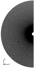
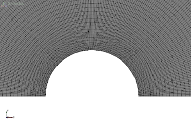
This section explains the procedure to remesh the volume based on the shape of the 2-D profile through expressions. The initial mesh is a half annulus with an inner radius r as shown in Figure 9.21. The mesh is clustered with finer near cells near the inner circle. This mesh is now deformed based on the inner profile shape.
To know more about how Mesh Deformation works, click Description drop-down list.
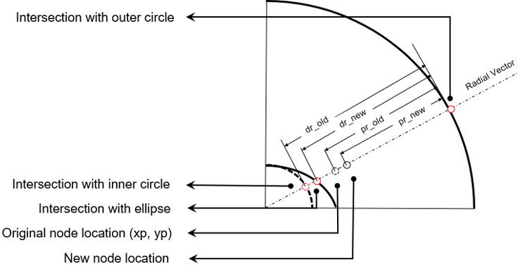
For any mesh point, consider a vector that starts from the center of the original mesh circle, passing through the original location of the point, and finally hitting the outer circle. This vector intercepts with the original inner circle, as well as the corresponding ellipse as shown in Figure 9.23. The new node will still lay on the same vector, except at a different distance from the outer circle. The distances satisfy the following relation.

|
Algorithm finding intersection
For a point with coordinates ( ,
,  ), the radial vector starts from origin go through the current point can be defined in a parametric form:

|

|
where  is a parameter, and

|
Substitute equation 9.17 and equation 9.18 into equation 9.5 to get a quadratic equation solving for  :
:

|
Where,

|
The radius at the intersection with the ellipse is obtained by solving equation 9.20 and using only the positive values of the solution. Now, the new radius for each mesh point and their corresponding coordinates can be obtained using equation 9.16. An example of deformed mesh obtained using the new coordinates according to the shape of a non-circular 2-D profile is shown in Figure 9.24.