Boundary Conditions
|
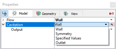
The boundary condition parameters for the Cavitation module apply to Boundaries as well as Interfaces that are Blanked on one side in the Flow module. The boundary conditions and associated Cavitation parameters are specified as follows:
|
Figure 5.75 - Boundary conditions |
| Gas Mass Fraction | Vapor Mass Fraction | Dissolved Gas Mass Fraction | Output | |
|---|---|---|---|---|
| Wall | No | No | No | Yes, for all models |
| Symmetry | No | No | No | Yes, for all models |
| Specified Value | Yes, for Variable Gas Mass Fraction and Full Gas Model | Yes, for all models | Yes, for Dissolved Gas Model and Full Gas Model | Yes, for all models |
| Outlet | Yes, for Variable Gas Mass Fraction and Full Gas Model | Yes, for all models | Yes, for Dissolved Gas Model and Full Gas Model | Yes, for all models |
Wall
On a solid wall boundary, zero-flux or gradient condition applies for the mass fractions of vapor , NCG and dissolved das, depending on the cavitation model selected. No direct user inputs are required.
Symmetry
For a physical symmetry, zero-flux or gradient condition applies for the mass fractions of vapor, NCG and dissolved gas, depending on the cavitation model selected. No direct user inputs are required.
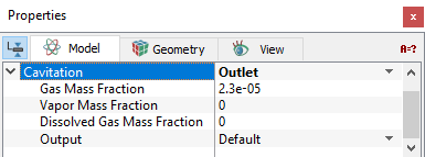
OutletAt a flow outlet (Specified Pressure Outlet or Resistor Capacitor), the mass fraction values are specified for the vapor, NCG and dissolved gas, depending on the cavitation model selected. However, the specified values are only used when back flow (flow entering the domain through the outlet) occurs. If the flow is to exit the outlet, zero-flux or gradient conditions apply. Depending on the Cavitation model selected, the actual mass fraction inputs are listed in Table 5.21. |
Figure 5.76 - Outlet options |
| Gas Mass Fraction | Vapor Mass Fraction | Dissolved Gas Mass Fraction | |
|---|---|---|---|
| Constant Gas Mass Fraction | Yes | ||
| Equilibrium Dissolved Gas Model | Yes | ||
| Variable Gas Mass Fraction | Yes | Yes | |
| Dissolved Gas Model | Yes | Yes | |
| Full Gas Model | Yes | Yes | Yes |
Inlet
At a flow inlet (Specified Velocity, Specified Volumetric Flux, Specified Total Pressure or Specified Pressure Inlet), Specified Values are applied for the mass fractions of vapor, NCG and dissolved gas, depending on the cavitation model adopted (Table 5.21). As in the Outlet condition, however, if the flow is to leave the boundary, zero-flux or gradient conditions actually apply at the Inlet.
Specified Values
|
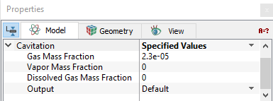
This is used whenever the Vapor Mass Fraction, Gas Mass Fraction and / or Dissolved Gas Mass Fraction are known, or the default value is acceptable. The inputs for Specified Values are mass fractions. This is the default boundary condition, if Specified Velocity, Specified Volumetric Flux, Specified Total Pressure or Specified Pressure Inlet is selected under the Flow module. Based on the Cavitation model selected, the mass fraction inputs for a boundary change as shown in Table 5.21. The mass fraction of the Gas Mass Fraction, Dissolved Gas Mass Fraction and/or Vapor Mass Fraction for any fluid exiting the domain is based on respective internal (upwind) mass fraction. For any fluid entering the domain, it is based on the value specified for the selected boundary. The mass fraction of the above specified at the outlet can influence the internal mass fraction via diffusion. Typically, this effect is insignificant unless the outflow is either very small or the conductivity very high. |
Figure 5.77 - Specified values options |
Interface Conditions
For a fluid-solid interface (Blanked on one side in the Flow module), it is treated as a wall boundary for the flow, and zero-flux or gradient conditions apply for the mass fractions of vapor, NCG and dissolved gas, depending on the cavitation model adopted. For a fluid-fluid interface, it is then considered as face connection between interior cells, and no boundary conditions are required.