Boundary Conditions
|
The boundary condition parameters for the Turbulence module apply to Boundaries. The options also apply to Interfaces for which the Flow module is Blanked on one side of the interface, creating in effect, a boundary. The boundary conditions and associated Turbulence parameters are specified as follows: |
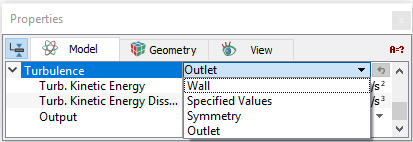
Wall
This corresponds to a solid boundary and is the default Turbulence condition for the boundary whenever Wall is selected in the Flow module.
Wall functions
The different Wall Functions for the near-wall treatment are shown below:
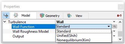
Note: Ideally to use wall functions, the height of the first cell center should be placed at a non-dimensional normal-to-wall distance,  . For more information, refer Wall physics. . For more information, refer Wall physics. |
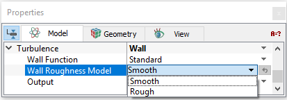
Wall Roughness Model
|
In Simerics-MP, the wall shear can be made a function of wall roughness using the Wall Roughness Model. The Wall can be modelled as either of these two:
The outputs available with the Wall boundary condition include Area, Normal, and Y Plus. |
Figure 5.64 - Turbulence Wall Roughness Model |
Outlet
|
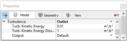
This allows the user to set the Turbulent Kinetic Energy (TKE) and the Turbulent Energy Dissipation Rate (TKEDR) at the outlet boundary. These influence the internal TKE and the TKEDR via diffusion. Typically, this effect is insignificant unless the outflow is either very small or the conductivity is very high. |
Figure 5.65 - Turbulence Outlet |
|
Note: The Outlet boundary condition is the default condition for the Turbulence module whenever a Specified Pressure Outlet or Resistor, Capacitor boundary condition is selected for the Flow module. |
Specified Values
Specified Values can be used as a Turbulence boundary condition whenever the TKE and the TKEDR at a boundary are known or the default value is acceptable.
The TKE and the TKEDR of any fluid entering the domain is based on the values specified for this boundary. The specified values at an Outlet can influence the internal TKE and the TKEDR via diffusion. Typically, this effect is insignificant unless the outflow is either very small or the conductivity is very high.
The default values of TKE and the TKEDR are 0.01 (m2/s2) and 1 (m2/s3) respectively.
|
Note: The Specified Values boundary condition is the default condition for the Turbulence module when a Specified Velocity, Specified Volumetric Flux, Specified Total Pressure, or Specified Pressure Inlet is selected for the Flow module. |
Symmetry
This means that there is no flux or gradient of the TKE at the Boundary. This usually corresponds to a physical symmetry in the model, but it doesn’t have to, as long as the effects of this boundary condition make sense.
|
Note: The Symmetry boundary condition is the default Turbulence condition for the boundary whenever a Symmetry boundary condition is selected for the Flow module. |
Interface Conditions
The Interface parameters and outputs for the Turbulence module are the same as those for the Boundaries, if and only if the interface separates a solid and fluid (one side of the Interface has been Blanked for Flow). If the Interface separates two solids or two fluid volumes, i.e if the Flow module is Active on both sides of an interface, the interface treatment is the standard treatment between two internal cells (assigned as a Default Interface).