|
You are here: Automotive Templates and Tutorials > Automotive Tutorials > Journal Bearing Tutorial > Setting up the model
|
Setting up the model
This section describes step-by-step, the definition of the computational domain, mesh and the physics for the bearing simulation.
In this tutorial, oil gallery, groove and cross drill geometries are imported into Simerics-MP+ by importing the project file. The shaft bearing and connecting rod bearing do not require CAD Surfaces for meshing. These volumes are created during meshing using Template Mesh/Surface.
Importing the Geometry
The first step is to import the geometry or surfaces.
- Select File > Open. The file bearing_initial_cad_surfaces.spro is selected from the working directory in the Open Project dialog box, click Open.
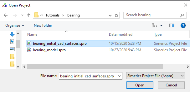
Figure 7.136 - Importing the geometry
| ´ | Note: To import .STL file refer to Import/Export Geometry or Grid. |
The steps involved in setting up the model are:
- Computational Domain: In the case of a bearing simulation, the computational domain is the internal fluid domain of the bearing.
- Building the Mesh: Once the domain is selected, a grid of sufficient resolution is created to solve the flow.
- Defining Physics & Conditions: Defining the physics and the conditions for the problem.