|
You are here: Fluid Machinery Templates and Tutorials > Compartment Valve > Compartment Valve Model > Conditions
|
Conditions
This section explains the conditions related to the boundaries applied for Ball Valve and Spool Valve (Refer to Figure 6.521 for Spool Valve boundaries conditions) models.
The Ball Valve/Spool Valve compartment template has following boundary conditions. They are
Properties Panel > Model Tab > Ball Valve/Spool Valve > [Desired options].
The Compartment valves have following boundary conditions:
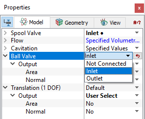
- Not Connected: As the name implies, the default boundary conditions of non connected for a boundary of the 3-D domain implies that boundary is not connected to the 1-D valve model. This boundary condition is present in Ball Valve or Spool Valve compartment module.
- Inlet: This boundary condition specifies an inlet boundary for the 1-D valve model for a boundary of 3-D domain. This boundary condition is present in Ball Valve or Spool Valve compartment module. The sense of the boundary type under the compartments module is relative to the valve. For example, the Inlet refers to the inlet to the valve and the outlet from the 3-D model domain.
- Outlet: This boundary condition specifies an outlet boundary for the 1-D valve model for a boundary of 3-D domain . This boundary condition is present in Ball Valve or Spool Valve compartment module. The sense of the boundary type under the compartments module is relative to the valve. For example, the outlet refers to the outlet from the valve and the inlet to the 3-D domain.
- Control BC: This boundary condition is for Ball Valve or Spool Valve that specifies a rotating volume with the same Rotational Axis Vector and Rotational Direction as the rotor chamber.
- Rotating Wall: This boundary condition specifies a control port of the 1-D valve model for a boundary of the 3-D domain. This boundary condition is present in Spool Valve module.
- Wall: This boundary condition specifies a wall boundary for the Ball Valve or Spool Valve. A Wall is a default boundary condition in the flow module for a Ball Valve or Spool Valve Wall boundary.
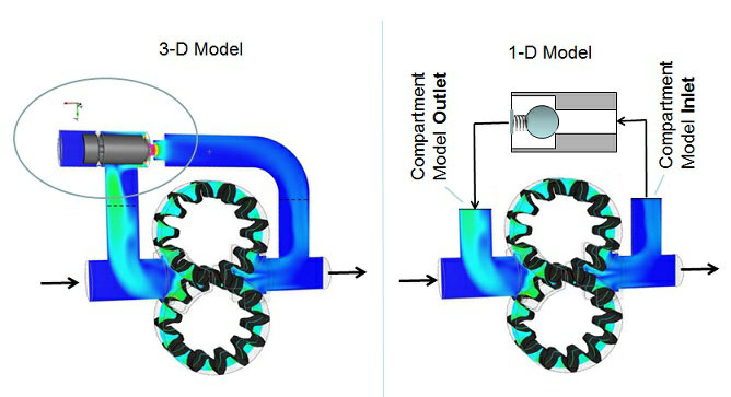
Figure 6.780 - Ball valve compartment module-Inlet |
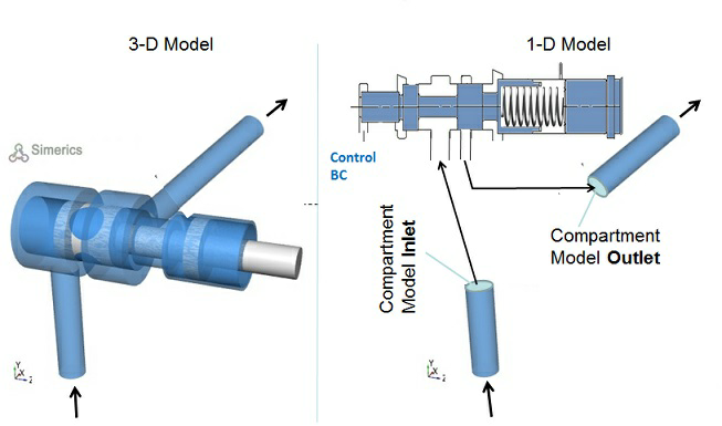
Figure 6.781 - Spool valve compartment module-Inlet |
|
Note: The default values in each module under the template can be accessed and modified, by using the Extended Mode. |
Output
Primary and Derived variables can be integrated over a selected boundary and stored in the ASCII format file filename_integrals.txt for subsequent post-processing. These data can also be displayed real-time in the GUI using the X-Y Plots feature. The quantities available for output for the boundary depend on the boundary type as listed below:
- Ball Valve: Area, Normal, Displacement, Velocity, Net Force.
- Spool Valve: Area, Normal, Displacement, Velocity, Net Force, Control Pressure, End Pressure.
The desired output can be activated for a selected boundary in the Model Tab of the Properties Panel. The outputs which can be activated are specified as User Select(Area, Normal).
The Output Properties other than User Select, are automatically calculated and stored in the output file as Filename_integrals.txt and may be selected and displayed in an X-Y Plots.
When monitoring Points are created as part of the simulation, the output quantities are stored in the ASCII format file filename_points.txt for subsequent post-processing.
|
Note: One dynamic component boundary is selected to output either one of these variables-Displacement, Net Force or Velocity. Summing multiple boundary conditions will give an incorrect value. |