4.4 Mesh Movement
Mesh movement is the time dependent change of volume mesh to solve transient flows. This is achieved using the Volume Remesh feature in Simerics-MP/Simerics-MP+.
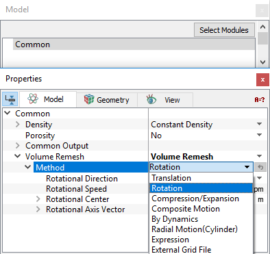
Specify the method of mesh movement as follows:
|
Note: The effect of boundary motion due to remesh is not automatically included in the shear terms for the flow module. Shear effects must be accounted for by correct specification of the corresponding Boundary Condition (BC) in the flow module. (For example, a rotating wall must be given the Flow BC = Rotating Wall.) |
For brief description of each method, click the respective Method or click Description drop-down list.
Translation
|
This method translates a selected volume and associated mesh. The motion is defined by a Displacement or a Velocity. The associated methods under Options are:
|
Figure 4.108 - Method-Translation |
 vector or as a function of time (using the
  vector or as a function of time (using the
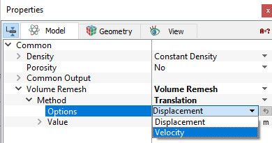
|
Example: The Translation motion, using volume remesh is simulated as follows:
|
Figure 4.109 - Animation-Translation |
 co-ordinates under
Rotation
 coordinate lying on the rotational axis.
  values are the components of the
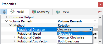
|
Example: The Rotation motion, using volume remesh is simulated as follows:
|
Figure 4.111 - Animation-Rotation |
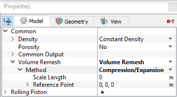
Compression/Expansion
|
This method deforms a volume based on a Scale Length and Reference Point. Compression/Expansion motion stretches the shape of the selected volume uniformly in all three directions around a Reference Point
Figure 4.112 - Compression/Expansion The parameters associated with the Compression/Expansion are Scale Length and Reference Point.
|
Figure 4.113 - Method-Compression/Expansion |
 using the following equations shown in
|
Example: The Compression/Expansion motion, using volume remesh is simulated as follows:
|
Figure 4.114 - Animation-Compression |
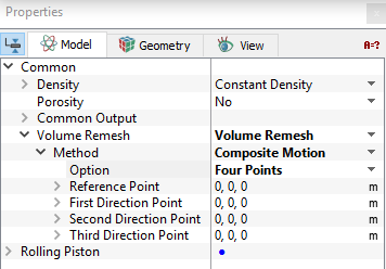
Composite Motion
|
This method deforms a volume based on a Reference Point and One, Two, or Three direction points. This method stretches the shape of the selected volume using a reference point and one, two, or three “tug” points that stretch the |
Figure 4.115 - Method-Composite motion |
 coordinate system as if elastic.
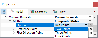

Figure 4.116 - Composite motion
|
There are three methods under Option for Composite Motion:
The Directional Points are defined as functions of time using the expression editor. The Reference Point can be stationary or a function of time. |
Figure 4.117 - Composite motion-Parameters |
For example, the effect of a direction point,  , on a point A in the volume is based on the Reference Point,
  , as follows:

|
4.1 |

|
4.2 |

|
4.3 |
|
Example: The Composite motion, using volume remesh is simulated as follows:
f=2
xx=0.2+0.1*sin(2*3.14*time*f) |
Figure 4.118 - Animation-Composite |
By Dynamics
This method deforms/moves a volume as a function of time based on motion defined using a selected Dynamic module.
|
Note: At least one Dynamics module (e.g. Translation (1-DOF) or Rotation (1-DOF)) must have been activated for By Dynamics to have an option for controlling the motion. |
|
Example: The Dynamics motion, using volume remesh is simulated as follows:
|
Figure 4.119 - Animation-By dynamics |
Radial Motion(Cylinder)
|
This method deforms the annulus volume based on movement of inner cylinder with respect to stationary outer cylinder. The control parameters associated with Radial Motion(Cylinder) are:
|
Figure 4.120 - Method-Radial motion(Cylinder) |
 function to displace the moving cylinder.
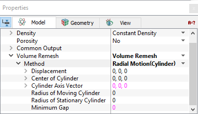
|
Note: When creating the mesh, it is compulsory to create a concentric annulus and then deform it. |

Figure 4.121 - Radial motion(Cylinder)
The Radial Motion (Cylinder) option was originally developed for the relative motion between a journal bearing and its shaft (a deforming annulus such as shown above), but can be used to deform any mesh between two reference cylinders. Only radial displacement of the moving cylinder has any effect on the mesh/ volume deformation.
|
Example: The Radial motion (Cylinder), using volume remesh is simulated as follows:
f= 2
amp=0.01 xx=amp*sin(2*3.14*time*f)
yy=amp*cos(2*3.14*time*f) |
Figure 4.122 - Animation-Annulus |
The Displacement of the moving cylinder is defined using the Expression Editor as follows:

Figure 4.123 - Moving cylinder-Expression editor
As illustrated for the cube below, only the /volume between the reference cylinders is deformed:

Figure 4.124 - Mesh/Volume between the reference cylinders
Expression
This method is used to deform a volume based on user-defined expressions for the  coordinates. This moves the
  coordinates of a selected volume and associated mesh as a function of time, based on expressions for each coordinate. The new coordinate positions are based on their original coordinates
  which themselves do not change during remeshing. To find the example using expressions, see this reference.
|
Example: The motion using an expression is simulated using the following steps.
|
Figure 4.125 - Animation-Expression |
External Grid File
|
The deformation of a volume is specified through external files in this method. The The entries associated with External Grid File are:
|
Figure 4.126 - Method-External grid file |
 coordinates of a selected volume and associated mesh move as specified by an
  coordinates in the external file.
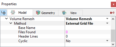
|
Note: The name of the external grid file should in the format of <BaseName><number>. The file contains the |
 coordinates with header line indicating the number of points in the corresponding file.