CFD分析
Tecplot 360 可帮助您分析计算流体动力学及菜单使用,包括:
-
函数计算,包括网格质量函数(如
-
输入或计算数据的积分,包括标量、
-
湍流变量计算。
-
粒子路径和迹线计算,包括带质量的
-
使用Richardson外推法进行误差分析。
-
流场特征检测,包括涡核、分离和
Units (Dimensions)
分析可针对任何单位制或量纲的数据进行,units工具进行单位转换。分析结果将采用与
指定流体属性
流体属性(如粘度)描述了用于创建对话框设置。输入的值必须在量纲上彼此一致,
对于包含多个数据集的布局,每个数据集和选项(位于菜单中)将设置从一个数据集, , 、对话框中进行的设置。
通过从可访问菜单中选择对话框。
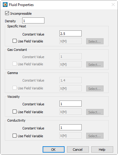
The 对话框允许您指定可压缩或不可压缩流体的属性。对于不可压缩(均匀密度)流体,您需要指定密度、比热、粘度和导热系数。对于可压缩(变密度)流体,您需要指定气体常数、伽马(比热比)、粘度和导热系数。
默认情况下,每个流体属性均为常数。然而,每个属性(密度除外)都可以被场(数据集)变量覆盖。当分配场变量时,该变量的局部值将用于使用该属性的场计算,而常数值仅用于全局计算,例如参考(自由流)量的计算。要为特定属性分配场变量,请设置切换开关并点击从当前数据集中选择一个变量,通过对话框。
- 不可压缩
-
开启此开关表示流体为不可压缩。对于不可压缩流体,您必须指定密度、比热、粘度和导热系数。对于可压缩流体,您必须指定气体常数、伽马、粘度和导热系数。
- 密度(for incompressible fluids only)
-
密度表示单位体积内流体的质量。其量纲为
- 比热(for incompressible fluids only)
-
比热是将单位质量的流体温度升高一度所需的能量。量纲为 .
- 气体常数(for compressible fluids only))
-
比气体常数的量纲为 .
- 伽马(for compressible fluids only)
-
伽马表示定压比热与定容比热的比值,是一个无量纲量。
- 粘度
-
动力粘度的量纲为 .
- 导热系数
-
导热系数的量纲为 .
指定不可压缩流体属性
当选中“不可压缩”复选框时,必须输入流体的密度及其比热( )、粘度( )和导热系数( )。伽马( ),即定容比热与定压比热的比值,对于不可压缩流体为1,因此伽马部分处于非活动状态。气体常数( ) 也处于非活动状态。不可压缩流体的热状态方程和量热状态方程如下所示。 为密度, 表示单位质量的内能。
由于在对话框中输入的密度代表整个物理域中流体的密度,因此不允许在对话框中输入密度的参考值,也不允许在Identifying State Variables).
Specific heat ( 对话框中选择密度场变量(参见
)。比热是将单位质量的流体升高一度所需的能量,其量纲为: 粘度(
)表示动力粘度系数,单位为 导热系数(
)是流体的热导率,单位为:
指定可压缩流体属性当未选中复选框时,必须输入气体常数、比热比、粘度和导热系数。由于密度不是可压缩流体的恒定属性,文本字段以及对话框中的 部分均处于非活动状态。可压缩流体的热状态方程和量热状态方程如下所示。 为压力,
| 为单位质量的内能:Identifying State Variables量热状态方程假设流体的比热为常数。当该假设不成立时(例如高温流动),Tecplot 360 将计算出不准确的温度值。对于此类情况,最好让求解器输出温度,然后将其输入到 Tecplot 360 中以供其他计算使用(参见 and )。如果您的解代表化学反应流动,求解器还应输出Specifying Incompressible Fluid Properties. |
作为场变量,您可以按照本章前面
中的讨论进行识别。气体常数是通用气体常数除以流体的分子量:
其单位为:
处理无量纲数据
考虑一个案例,其中温度通过除以自由流温度进行无量纲化:
压力则通过伽马(比热比)和自由流压力进行无量纲化:
我们希望知道在对话框中应输入什么气体常数。我们将已知量代入热状态方程(其中 是密度, 是气体常数):
由于状态方程必须适用于自由流条件,我们知道:
由此可知,前一个方程中分母(1)和(2)的乘积必须等于 因此:
但这并未完全回答我们的问题,在缺乏额外信息的情况下,我们只需决定如何 and 分别进行无量纲化。我们刚刚确定的要求是,两者的乘积必须通过 进行无量纲化。因此,我们可以决定将密度按自由流密度进行无量纲化, 这样气体常数就被无量纲化(即除以) 。对话框中,我们输入 作为气体常数。如果我们选择将气体常数保持为1,则密度将通过伽马和自由流密度进行无量纲化。 .
指定参考值
某些计算(如压力系数,参见Calculating Variables)需要参考值或自由流值。如果您使用PLOT3D加载器加载数据,这些信息可能已随数据一同加载。否则,您可以通过 dialog.
提供这些信息。对于包含多个数据集的布局,每个数据集会单独维护设置。您可以使用 and options in the 将设置从一个数据集复制到另一个数据集。这些操作还会传输在, , 和 dialogs.
中进行的设置。要显示对话框,活动帧中必须存在数据。对话框
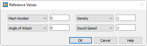
对话框选项如下:
- U 速度/马赫数
-
前两个文本字段中,您可以将自由流速度指定为 U 速度和 V 速度,或指定为马赫数和攻角。(Z 速度假定为零。)攻角必须以度为单位指定;沿 +X 和 +Y 方向流动时攻角为正。对于不可压缩流动(参见Specifying Incompressible Fluid Properties),只能指定 U 速度和 V 速度。
- 压力/密度
-
第三个文本字段允许您指定或。在下拉菜单中选择相应选项。对于不可压缩流动,您必须指定,因为密度已在 dialog.
- V 速度/攻角
-
如果第一个字段设置为 U 速度,则将此字段设置为 V 速度。如果设置为马赫数,则将此字段设置为攻角。
- 温度/声速
-
最后一个文本字段允许您指定温度或声速。温度必须使用绝对单位,例如开尔文或兰氏度。对于不可压缩流动,您必须指定温度。对于不可压缩流体,声速未定义,流体密度为常数。
识别场变量
数据分析针对活动帧中的数据执行。其中许多计算需要了解数据所代表的信息。例如,如果您希望根据数据计算压力,则必须识别另外两个热力学状态变量,Tecplot 360 可使用这些变量通过热状态方程执行计算。X、Y 和 Z 取自活动帧中 2D 或 3D 图的轴分配。FLUENT 和 PLOT3D 数据加载器将剩余的大部分或全部信息提供给 Tecplot 360。您也可以使用 dialog.
For a layout with multiple datasets, separate settings are maintained for each dataset. You can copy the settings from one dataset to another using the and 菜单中的选项提供此信息。这些操作还会传输在, , , and dialogs.
中进行的设置。您必须在活动帧中有数据才能打开对话框。对话框如下所示。
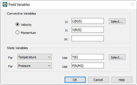
对话框顶部区域允许您指定对流变量向量,即速度或动量(速度乘以密度)。对话框底部区域包含两个下拉菜单及关联的文本字段,用于识别数据集中的两个热力学状态变量。
| 在 Field Variables 对话框中选择的变量是每单位体积的变量。 |
选择对流变量
通过单击选择数据集中的对流变量。按钮位于对话框的顶部区域。对话框中选择两个选项之一,
| 数据分析中使用的对流变量not与用于为求解数据创建矢量图的变量相同,尽管它们的初始值可能设置为相同。 |
识别状态变量
The 对话框的, , , , ,或。然后点击,Specifying Incompressible Fluid Properties),您可以为一个变量指定压力,为另一个变量指定温度或滞止能量(每单位体积)。
| 温度必须使用绝对单位,例如开尔文或兰金。 |
The 按钮启动对话框,
设置几何与边界选项
对于某些计算,您需要指定 Tecplot 360 可能无法自动检测到的数据信息。例如,二维求解可能实际上代表三维轴对称求解,从而影响您执行的任何积分。相邻区域可能相互连接,影响其他计算,如网格拉伸因子、梯度和涡核等流动特征。某些区域或区域表面部分可能代表求解中的壁面边界,在这些边界上可以计算分离线和附着线。当您导入 FLUENT 案例和数据文件时,FLUENT 数据加载器会自动为您识别这些特征中的大部分。您也可以通过对话框(通过菜单访问)指定它们。
For a layout with multiple datasets, separate settings are maintained for each dataset. You can copy the settings from one dataset to another using the and options in the . These actions also transfer the settings made in the , , and dialogs.
您必须在活动帧中有数据才能启动对话框。从菜单中选择“Geometry and Boundaries”以显示该对话框。
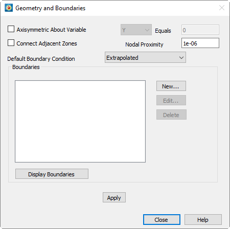
- 指定轴对称求解
-
选择启用下拉菜单,并允许您在“Equals”字段中输入值。从下拉菜单,并输入定义对称轴的该变量的常数值。若选择轴对称选项,所有积分将通过将积分函数乘以 [T0001] 来执行三维轴对称积分,其中 [T0002] 为到指定对称轴的距离。积分操作详见 [T0003] 连接相邻区域。 where is the distance from the specified axis of symmetry. Integrations are described in Performing Integrations.
- Connecting Adjacent Zones
-
Tecplot 360 可计算相邻区域(或同一区域)边界上的节点是否重叠。此信息用于计算 [T0005] 网格质量函数(参见 [T0006])、计算梯度以及提取流体流动特征(参见 [T0007])。区域间的连接按单元面逐一计算。当特定边界单元面的所有节点与相邻边界单元面的所有节点重叠时,这两个单元被视为已连接。 grid quality function (see I, J, K-stretch Ratio), calculating gradients, and extracting fluid flow features (see Extracting Fluid Flow Features). Connections between zones are calculated cell face by cell face. The two cells are considered connected wherever all nodes of a particular boundary cell face overlap all nodes of an adjacent boundary cell face.
对于非定常流动(参见 [T0009]),仅检查同一时间层内的区域连接。要启用此选项,请选择 [T0010] 选项,并在 [T0011] 文本字段中输入两个节点被视为重叠的最大距离。注意,该文本字段的值也用于下文讨论的区域类型边界。Unsteady Flow), only zones within the same time level are examined for connections. To enable this option, select the option and enter the maximum distance at which two nodes will be considered to overlap in the text field. Note that this text field value is also used for zone-type boundaries, discussed below.
区域连接功能会逐单元地被数据集中包含的面邻接关系覆盖。这两种连接机制均会被特定面上设置的任何边界条件覆盖。也就是说,若在 [T0013] 对话框中为特定单元面指定了边界条件,则该面不会与相邻单元连接,无论是否存在面邻接关系或重叠节点。 dialog that covers a specific cell face, that face will not be connected to an adjacent cell, irrespective of any face neighbors or overlapping nodes present.
性能注意事项
建立跨区域边界的连接使 Tecplot 360 能在这些位置计算更精确的梯度量。对于有序区域计算,可能会产生显著的性能开销,因为在这些边界位置,Tecplot 360 使用有限元最小二乘法公式计算梯度。梯度计算的讨论请参见 [T0016]。Gradient Calculations for a discussion of gradient calculations.
指定边界与边界条件
您可以将单元边界面(区域外部的单元面)与边界条件关联。执行此操作的原因有二:
-
确保边界面不与相邻单元连接(参见上述关于连接的讨论)。
-
在三维解中识别壁面边界以进行特征提取(参见 [T0021])。若在特定单元边界面上设置边界条件,梯度计算程序将不会认为该面与任何其他单元连接。例如,在包含薄平板的解中,平板两侧的节点重叠,若不设置边界条件,连接机制会将其连接,而设置边界条件可避免此情况。Extracting Fluid Flow Features).
If you set a boundary condition on a particular cell boundary face, that face will not be considered connected to any other cells by the gradient calculation routines. This may be advantageous, for example, in solutions containing a thin flat plate, where nodes on either side of the flat plate overlap and would otherwise be connected by the connection mechanism.
对于三维流动解,可使用 [T0023] 对话框提取分离线和附着线。这些线仅在被识别为壁面边界的边界上计算。虽然可指定其他边界条件,但除抑制连接外,此信息目前暂未使用。 dialog to extract separation and attachment lines. These lines are only calculated on boundaries you have identified as wall boundaries. While other boundary conditions may be specified, this information is not currently used, aside from inhibiting connections.
指定默认边界条件
Tecplot 360 会跟踪所有未连接的边界单元面(参见Setting Geometry and Boundary Options)。对于未按下文所述方式指定边界的未连接面,系统将应用默认边界条件。请从下拉菜单中选择所需的边界条件。默认边界条件位于边界"优先级顺序"的底部。如果某个单元边界面未被任何其他边界条件覆盖,且未通过连接设置或 Tecplot 360 面邻接关系连接到其他单元,则系统将对其应用默认边界条件。
Identifying Zone Boundaries
区域边界上的区域可被显式标识并与特定边界条件关联。仅对于有序区域,您可以通过区域边界(即 I=1 边界)及该边界上的索引范围来标识边界区域。对于所有区域类型,您可以通过选择一个或多个边界区域来标识边界区域。
边界区域是维度比当前绘图类型少一的区域。在 3D 笛卡尔绘图中为曲面,在 2D 笛卡尔绘图中为线。当这些边界区域的节点与 3D 笛卡尔绘图中体区域的边界节点或 2D 笛卡尔绘图中曲面区域的边界节点重合时,即认为存在边界。例如,您可以使用位于四面体(3D)区域表面的三角形区域来标识该四面体区域上的边界区域。当三角形区域的节点与四面体区域的边界节点重叠时,即应用该边界。与连接相邻区域类似,匹配过程通过逐单元面进行,并使用对话框的设置来确定节点需接近到何种程度才被视为重叠。
通过从数据集中的有序区域提取子区域,可以轻松创建边界区域。对于有限元区域,可以使用消隐和有限元边界提取来提取所需的边界区域。但通常,有限元边界区域必须来自网格生成器或流求解器。
通过单击对话框上的 New 按钮创建新边界。这将显示The Edit Boundary dialog,如下所示。
显示边界
可通过单击 [Display Boundaries] 按钮显示对话框的当前设置。这将创建一个新帧并绘制所有区域边界。对于求解数据中的每个区域,将在新帧中为该区域边界面应用的每个边界条件创建一个区域。这些区域的名称指示其在求解数据中的源区域以及所应用的边界条件。
对于求解中的每个边界面,Tecplot 360 会应用一些简单规则来确定该面的边界条件。首先,边界列表中边界定义覆盖的所有面都将应用列表中指定的边界条件。如果某个特定面被多个此类边界覆盖,则列表中位置较低的边界优先。如果您选择了选项,则会检查未被列表边界覆盖的面是否与相邻区域的面重叠。重叠的面将被分配边界条件"区域间边界"。最后,任何未分配其他边界条件的边界面都将被分配您选择的默认边界条件。
由于对话框是非模态的,您可以在应用设置之前探索此新帧中的边界定义。这是确保您应用所需边界设置的便捷方式。
如果您正在录制宏文件,选择 [Display Boundaries] 按钮会记录一条DISPLAYBOUNDARIES宏命令。
由于此功能会创建新帧,因此无法保存在数据日志中,并且当前数据日志将失效。如果您随后保存布局文件,系统将提示您保存新的数据文件。
编辑边界对话框
The 对话框通过点击上的对话框,或通过.
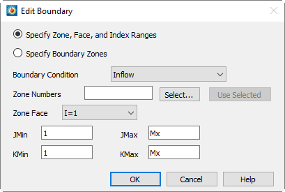
显示。它允许您通过Setting Geometry and Boundary Options所述。输入所需以将边界添加到 dialog.
使用索引范围型边界
对于有序区域,您可以通过选择区域Performing Integrations了解对话框的说明。)如果您通过在工作空间中单击输入这些区域编号。从 Zone Face时,新边界将以以下格式出现在 Boundaries 列表中:
<bc>,<set>,<face>,INDEX1MIN,INDEX1MAX,INDEX2MIN,INDEX2MAX
<bc>是边界条件,为以下之一:Inflow,
Outflow, Wall, Slipwall,
Symmetry, and Extrapolated. <set>是边界所应用的区域编号集,用方括号括起来。<face>是以下之一:I=1,
I=IMAX, J=1, J=JMAX,
K=1, and K=KMAX其余参数
Wall,[2,4-6],J=1,1,0,3,-2
使用边界区域型边界
对于所有区域类型,您都可以标识边界区域,如Setting Geometry and Boundary Options所述。启用 Specify
<bc>,<set>
where <bc>如上所述,且<set>是
非定常流动
Tecplot 360 可以对非定常流动解执行粒子路径和流线计算。要启用此功能,它必须知道 dialog.
For a layout with multiple datasets, separate settings are maintained for each dataset. You can copy the settings from one dataset to another using the and options in the menu. These actions also transfer the settings made in the , , , and dialogs.
The 对话框中输入此信息,如下所示,该对话框通过选择在 menu.
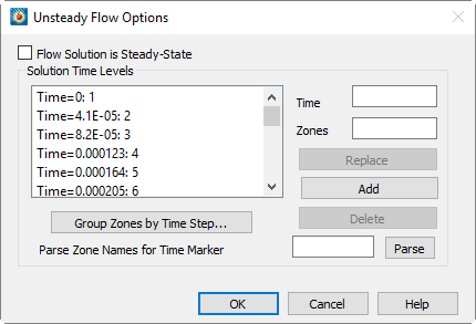
它包含一个选项,允许您指定解为稳态,一个用于显示您输入的非稳态时间级别的列表,以及用于输入新时间级别的控件。
指定稳态解
要让 Tecplot 360 将您的数据集视为稳态解,请选择选项。此设置将禁用对话框的其余部分。
要让 Tecplot 360 将您的数据集视为非稳态解,请取消选中这将启用对话框的其余部分,您可以在其中标识解的时间级别。
非稳态流动解由一系列表示连续解时间的区域组成。每个时间级别可以由一个或多个区域表示。通过在文本字段中输入特定解时间级别的区域编号,并在文本字段中输入它们表示的时间,然后选择 [Add],即可标识解时间级别。区域和关联时间将显示在列表中。您可以通过在列表中选择现有时间级别来编辑它。其时间和区域将显示在文本字段中,您可以在其中进行编辑。单击 Replace 将使用修改后的时间级别更新当前选中的列表时间级别。
通过在文本字段中手动输入每个时间及其关联区域,您可以标识当前数据集中的所有解时间级别。对于大量区域,还提供了另外两种输入时间级别的方法。如果您的解(或其部分)是使用恒定时间步长计算的,您可以使用Group Zones by Time Step Dialog一次性输入所有这些时间级别。或者,如果您的区域名称包含每个区域所代表的解时间,您可以通过解析区域名称中对应的解时间来输入所有时间级别。这些选项将在下面讨论。
按时间步长分组区域对话框
The 对话框允许您将一系列解时间级别输入到Unsteady Flow对话框中,比手动输入每个时间级别更简便。
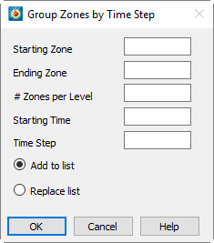
- Starting Zone
-
输入您希望包含在分组操作中的解数据的第一个区域。
- Ending Zone
-
输入您希望包含在分组操作中的解数据的最后一个区域。
- Zones per Level
-
输入每个解时间级别代表多少个区域。
- Starting Time
-
输入将分配给在此操作中标识的第一个区域或区域组的解时间。
- Time Step
-
输入求解的时间步长。每个时间层的求解时间将通过将当前时间步长添加到上一时间层的求解时间来计算。
- 添加到列表
-
启用此选项可将此操作识别的所有时间层添加到已存在的任何时间层中。如果任何新层计算出的时间已存在于列表中,将生成错误。
- 替换列表
-
启用此选项可用此操作识别的时间层替换列表中的所有时间层。
计算变量
PLOT3D函数可创建源自CFD网格和求解数据的数据集变量。这组函数最初出现在NASA的PLOT3D程序中,并在其后续版本FAST中得到扩展。函数包括网格质量度量以及标量和矢量流变量。完整函数列表请参考Calculate Variables Reference。这些函数通过以下方式计算: dialog.
其中许多计算受以下设置影响: dialog (see Specifying Fluid Properties)、 dialog (see Specifying Reference Values)和 dialog (see Identifying Field Variables)
要显示对话框,活动帧必须包含数据集。如下所示的对话框可通过选择以下选项显示: in the menu.
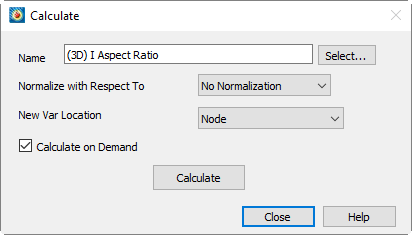
- 名称
-
此文本字段指示将用于计算的函数。输入所需函数的名称,或单击从所有可用函数列表中选择(参见Selecting a Function对话框)。或者,您也可以输入等效的PLOT3D函数编号,如Calculate Variables Reference.
- 函数归一化
-
函数可通过以下两种方式之一进行归一化:
- 最大幅值
-
将每个网格点的函数值除以幅值最大值,使得函数的绝对值始终不大于1。对于矢量函数,每个矢量分量除以最大矢量长度。
- 参考值
-
将每个网格点上的函数值除以使用参考值(在对话框的部分输入的值)计算的同一函数值。这是PLOT3D在其归一化函数中执行的归一化类型。此选项不适用于网格质量函数,因为这些函数不存在有意义的参考值。也不适用于参考值为零的函数,例如压力系数。
- 无归一化
-
选择以禁用归一化。
- 新变量位置
-
您可以通过下拉菜单选择计算过程中创建的新变量的位置(节点或单元中心)。数据集中已存在的变量将保持其原有位置。
- 按需计算
-
此选项将所选变量添加到数据集中,但将实际计算延迟到需要时再进行。下文将对此进行更详细的讨论。
- 计算函数
-
Selecting 对活动帧中的每个区域执行计算。如果这是首次计算所选函数,则会向数据集中添加一个以该函数命名的新变量。否则,系统将提示您用新值覆盖先前计算的变量。对于向量函数,函数的每个分量都会添加到数据集中,变量名称前会加上
X,Y, andZ前缀,并从名称中移除(vector)。如果函数已归一化,则根据所选选项,变量名称后会附加(Max-Normalized)or(RV-Normalized)。计算完成后,您将收到新变量的最小值和最大值及其位置的通知。
共享变量
如果启用了变量共享,则用于计算函数的所有变量在多个区域之间共享,并且这些变量以及计算出的变量都位于相同位置(单元中心或节点),则新变量也将被共享。您可以在 dialog (accessed via the menu).
按需计算变量
中使用按需计算选项计算的变量会添加到数据集中,但直到需要时才进行计算。在处理非稳态解时,这可以节省大量时间,因为任何给定时间只显示少量区域。显示计算变量的等高线图只会导致对当前活动区域进行计算。激活新区域(例如,通过推进Tecplot 360中显示的求解时间)将导致仅对新显示的区域进行计算。
| 如果您希望强制一次性对所有区域计算该变量,可以关闭按需计算选项后重新执行计算。 |
按需计算变量是数据集中其他变量的函数,并使用对话框进行计算。每当按需计算变量所依赖的变量被重新计算时,该变量也会被重新计算。例如,给定 = f(),如果的值发生变化,将被重新计算。
| 您无法修改按需计算的变量。 |
为避免循环数据依赖,系统禁止您在以下对话框中选中按需计算变量: or 此外,您不能删除任何按需计算变量所依赖的变量。
如果您计划对数据和分析设置进行一系列更改,可以通过关闭 Tecplot 360 的自动重绘功能来抑制这些自动重新计算。重新计算将仅在您重绘帧时进行。
选择函数
函数名称可输入到以下文本字段中:文本字段,或从包含所有可用函数的列表中选择。点击 [Select] 显示: dialog.
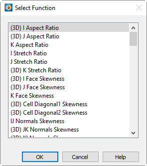
从此对话框中选择一个函数并选择 [OK] 后,该函数将输入到相应区域。列表中仅适用于 3D 解算数据的函数以以下内容开头:向量函数(其名称附加了以下内容)计算三个向量分量:(3D)每个可用函数的说明详见:(vector)选择函数的另一种方法是输入其等效的 PLOT3D 函数编号。这些编号也可在以下位置找到:Calculate Variables Reference.
如果在以下对话框的文本字段中输入有效的函数编号:Calculate Variables Reference文本字段对话框Tecplot 360 会将编号替换为对应函数的名称,并根据需要将 Normalize 下拉菜单设置为: or 适当的值。
梯度计算
大多数 PLOT3D 函数为标量函数。梯度计算是此规则的显著例外,它依赖于相邻点的值。了解这些计算方式有助于您解读结果。
有序区域中的梯度
除下文讨论的边界节点外,有序区域中的梯度使用标准有限差分公式计算。例如,在有序区域中计算特定节点的压力梯度时,使用以下公式:
Where 表示 I 方向, 表示 J 方向, 表示 K 方向,下标表示偏导数。在区域内部,导数采用二阶中心差分进行估算,例如:
or
左侧形式用于计算节点处的梯度,右侧形式用于计算单元中心处的梯度。
对于有序区域的边界节点,如果未在“几何与边界”对话框中指定为边界的一部分,则首先检查这些节点是否位于通过面邻接连接到其他单元的边界面上。如果不是,并且“几何与边界”对话框中设置了“连接相邻区域”选项,则检查该节点位置是否与相邻区域的任何边界节点重合。如果满足任一条件,则使用下文针对有限元区域描述的方法计算该节点的梯度。否则,其梯度使用标准单侧(一阶)有限差分计算。
有限元区域中的梯度
在未连接的有序区域中使用的坐标变换方法通常不适用于有限元区域。相反,假设变量(例如压力)在所有维度上线性变化,得到:
where 是所讨论节点或单元中心处的压力。接下来,形成一个矩阵方程,其中包含当前节点所有相邻节点的压力差(关于如何找到这些相邻节点,请参见下文)。
为了减少远离计算值的节点的影响,该矩阵方程的每一行 i 按以下方式缩放:
Where 是从节点i到目标位置(节点或单元中心)的距离,并且:
该方程通常是超定的,通过最小二乘法求逆得到梯度向量。
如果计算的是单元中心梯度,则上述矩阵方程中的每一行由构成该单元的节点处的值计算得出。如果计算的是节点中心梯度,则使用通过单元边连接到该节点的所有节点。如果节点位于区域边界上,且未被“几何与边界”对话框中指定的边界覆盖,则采取两个额外步骤以在区域边界上获得更连续的梯度:
-
如果该节点是通过面邻接连接到其他单元的面的组成部分,则也使用那些相邻单元的节点;
-
否则,如果“几何与边界”对话框中启用了“连接相邻区域”选项,则检查该节点位置是否与相邻区域中的边界节点重合。如果是,则也使用通过单元边连接到该节点的所有节点。
表面法线计算
使用 Tecplot 360 的 CFDA 变量计算功能,您可以计算并在绘图中显示表面法向量。这包括以下步骤:
-
在对话框中,使用“单元中心”作为新变量位置,计算“网格 K 单位法向量(矢量)”。
-
打开矢量图层,选择刚计算的矢量的分量作为矢量分量。
-
In the 在对话框的“点”页面中,选择“表面附近的单元中心”作为要绘制的点。
具体来说,上述步骤包括以下内容。
要计算法线,请从菜单中选择“计算变量”。在对话框中,选择“网格 K 单位法向量(矢量)”作为要计算的变量(为此,请单击“选择”按钮,在出现的列表中向下滚动找到“网格 K 单位法向量(矢量)”,然后单击它)。选择“单元中心”作为新变量位置,然后单击“计算”。
接下来,在"绘图"侧边栏中启用"矢量"图层以显示法向量,并选择要显示的计算矢量的分量。矢量对话框。首次启用矢量图层时会出现此对话框;您也可以通过菜单栏中的打开该对话框。要显示"网格K单元法向(矢量)"法线,请分别选择"X网格K单元法向"、"Y网格K单元法向"和"Z网格K单元法向"作为矢量图层的X、Y、Z分量。
最后,点击"绘图"侧边栏中的"区域样式"按钮,打开对话框。在该对话框中,切换到"点"页面,并从 menu.
| 下拉菜单中选择"表面附近单元中心"。如果希望在无法识别平面的绘图上显示法向量,请从菜单中选择"提取",然后选择"FE-边界"。在"提取FE-边界"对话框中,从源区域提取边界区域,随后即可使用提取的区域显示法向量。 |
执行积分
Tecplot 360 提供灵活的积分功能。您可以对标量数据集变量以及与网格单位法向或单位切向向量点乘的矢量变量进行积分,并可按单个时间步的区域或按时间序列进行积分。Tecplot 360 还预定义了多种积分类型(如质量通量),以简化积分过程。在有序区域中,可对单元体积、面面积或线进行积分;在有限元区域中,可对单元体积进行积分。此外,还可计算由作用在表面或表面组上的压力和粘性力引起的升力、阻力、侧向力及力矩。
| 积分功能在其用户界面中引用"单元体积"。在二维或一维区域中,分别使用单元面积或单元长度代替体积。 |
积分结果可显示在文本窗口中(随后可保存为文本文件),或绘制在框架中。若选择后者,积分图框架的解算时间将与原始框架的解算时间关联,并在积分图上显示标记网格线以指示时间步。所有功能均可通过对话框访问(通过).
| 打开)。其中许多计算受 dialog (see Specifying Fluid Properties设置的影响,以及对话框(参见Identifying Field Variables) and the dialog (see Setting Geometry and Boundary Options). |
)。变量或变量函数的积分采用梯形法,具有二阶精度。对于每个线段、面或体积单元,取相应节点或单元中心值的平均值,乘以单元长度、面积或体积,最后将结果累加至区域或指定子集,得到积分结果。
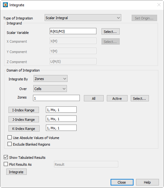
The 对话框通过选择 from the menu.

显示。该对话框提供积分区域、积分变量、积分域及显示方法的选项。
- 积分类型
-
Tecplot 360 可执行线积分、路径积分、面积分和体积分。请参阅Integrate Over了解如何根据当前绘图类型选择这些积分。Tecplot 360 定义了以下十四种积分类型:
- 长度/面积/体积
-
积分域的物理尺寸。
- 标量
-
单个变量的积分。
- 平均值
-
单个变量在域上的面积或体积加权平均值。
- 质量加权标量
-
单个变量乘以密度的积分。
- 质量加权平均值
-
以密度为权重函数的单个变量加权平均值。
- 加权平均值
-
通用加权平均值——需同时指定变量和权重函数。
- 标量流量
-
标量通过表面的对流。通过积分流速与表面单位法向量的点积再乘以标量变量计算。
- 质量流量
-
密度通过表面的对流。通过积分流速与表面单位法向量的点积再乘以密度计算。
- 质量加权流量
-
标量乘以密度后通过表面的对流。通过积分流速与表面单位法向量的点积再乘以标量变量和密度计算。
- 质量流量加权平均值
-
表面上标量变量的加权平均值。权重函数为流动动量向量(速度乘以密度)与表面单位法向量的点积。
- 力和力矩
-
表面上压力和粘性应力的积分。力和力矩选项对线(二维)和平面(三维)上的压力和剪切应力进行积分。压力假设作用于单位法向量的相反方向。通过积分应力张量与表面单位法向量的点积计算。例如,若二维翼型由
J=1线定义,且对 I 线(或 J 平面)进行力和力矩积分,则可正确计算升力和阻力。J=1.为正确计算粘性力,请确保已在流体属性对话框中设置粘度值。(参见Specifying Fluid Properties。)若流动为无粘流,应将粘度设为零以排除粘性力积分。
力和力矩计算为六个量:X、Y、Z 方向力以及绕原点的 X、Y、Z 方向力矩。为向后兼容,力也显示为升力、阻力和侧向力。升力和阻力为在 XY 平面内旋转后的力,其中升力垂直于参考流动方向(在对话框中指定),阻力平行于该方向。侧向力等于 Z 方向力。
若 I 有序区域(二维)或表面区域(三维)已被定义为表面(二维)或体积(三维)区域的边界,则可对该边界区域进行力和力矩积分。Tecplot 360 从关联区域获取剪切应力和单位法向量。例如,若存在定义表面的线或表面区域,并在 dialog.
- 向量点积法向
-
向量与表面单位法向量点积在曲面上的积分。此处向量的分量为数据集变量。
- 向量平均值
-
曲面上标量变量的加权平均值。权重函数为向量与表面单位法向量的点积。标量和向量分量均为数据集变量。
- 向量-切向点积
-
指定向量与线段单位切向量点积在直线上的积分。
涉及单位法向量的选项必须在可确定单位法向量方向的域内进行积分。可接受的域包括二维直线、三维平面,以及三维中的三角形或四边形区域。向量-切向点积选项仅能在直线上积分。单位法向量的进一步讨论请参见Surface Normal Calculations。 , 为段或单元质心到对称轴的距离。
涉及表面单位法向量的积分(如质量流量、力和力矩积分)依赖于指向一致方向(即朝向曲面区域同一侧)的表面单位法向量。有序曲面区域可保证这一点,但有限元曲面区域(三角形、四边形或多边形,包括提取的切片)则无法保证。对于这些区域,每个面的表面单位法向量方向通过右手定则结合该面的节点顺序计算。若某些面的节点按顺时针排列,而其他面的节点按逆时针排列(由区域的连接性定义),则这些面的表面法向量将指向不一致方向,任何依赖这些法向量的积分都不会产生有意义的结果。您可使用Surface Normal Calculations.
中描述的可视化表面单位法向量技术检查此情况。类似地,对多个曲面区域结果求和的积分可能无意义,因为一个区域的法向量可能与另一区域的法向量不一致。
- 被积函数
-
部分可用的积分类型要求您从数据集中选择要积分的变量。在需要时,对话框部分中的字段将被启用。您可输入变量名称,或单击"选择"(Select)来选取变量。
对于力和力矩积分,压力及速度分量由 dialog.
- 上标识的场变量计算得出。
-
积分域由区域或时间序列编号及索引范围定义。对于有序区域,您可选择在直线、平面或体积上进行积分。您还可选择使用计算体积的绝对值,这对于节点顺序可能导致错误计算的有限元区域非常有用。最后,您可选择排除因索引或值消隐而未显示的区域。有关消隐的更多信息,请参阅Blanking。
- 积分方式(Integrate By)
-
The 下拉菜单允许您指定按特定区域或特定时间序列进行积分。
- 积分范围(Integrate Over)
-
The 下拉菜单允许您指定单元、恒定 I、J 或 K 的平面,或变化 I、J 或 K 的直线。对于四面体和砖块型有限元区域,仅允许体积积分。对于四边形和三角形有限元区域,仅允许 K 平面(选择"单元"(Cells)等效于选择 K 平面,因为它们在逻辑上是二维的)。对于二维和三维笛卡尔绘图类型,直线上的积分作为路径积分执行,平面上的积分作为曲面积分执行。XY 线图中的积分沿 X 轴对所选变量进行积分,以计算曲线与 X 轴之间的面积。体积积分应在三维笛卡尔绘图中进行——二维笛卡尔绘图中的体积积分将得到零结果。
若需积分向量点积,则域必须具有可识别的法向或切向方向。在三维笛卡尔绘图中,这通常意味着选择 I、J 或 K 平面。这些情况下的法向量分别指向 +I、+J 和 +K 方向,对于左手系网格则方向相反。I、J 和 K 平面没有可识别的切向方向,因此在平面上进行向量-切向点积积分会产生错误。
若选择 I、J 或 K 直线,则切向量指向正索引方向。向量-法向点积积分也可用,但可能无意义——法向量通过切向量与 +Z 轴的叉积计算。
在二维笛卡尔绘图中,I 平面等效于 J 直线,J 平面等效于 I 直线,K 平面等效于单元。(在二维中最好忽略平面。)所有情况下均可使用法向和切向方向。但 K 平面的法向量指向第三维度;可能无意义。
对于四边形和三角形有限元区域,法线方向遵循右手定则——若右手手指沿从单元节点1到节点2再到节点3的方向弯曲,则拇指指向即为法线方向。
- 区域/时间序列
-
根据您选择按区域积分还是按时间序列积分,此文本字段允许指定变量积分所覆盖的区域或时间序列。您可以输入单个区域或序列、带连字符的范围(例如3-5),或这些的组合(用逗号分隔)。为方便起见,[All]按钮可将此文本字段设置为所有区域或时间序列。[Active]按钮将列出当前激活的所有区域或时间序列。您也可以通过点击从列表中选择项目,该操作会调出独立的选择对话框。
- 指定索引范围
-
在 or 字段下方是I、J和K索引范围。这些范围将应用于执行积分的每个区域。每个索引范围中的三个逗号分隔项分别表示起始索引、结束索引和跳跃因子。
对于有限元区域,仅J索引设置生效。这些设置指示执行积分的单元范围。基于下文讨论的原因,此类情况下跳跃因子设为1较为理想。
要输入或更改索引范围,请选择所需范围文本字段上方的按钮。此时将显示对话框。
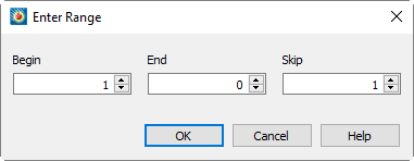
在字段中输入起始索引,在字段中输入结束索引,在字段中输入跳跃因子。
您有两种方式输入字段的内容。您可以输入一个数字,此时该对话框顶部会显示最大允许值,该值表示对话框中列出的所有区域中给定索引的最小尺寸。或者,您可以输入"Mx"以使用每个单独区域的最大索引,"Mx - 1"表示使用最大值减一,以此类推。跳跃因子为1表示"使用范围内的每个点",跳跃因子为2表示"每隔一个点使用一次",依此类推。
对于线性和平面积分,跳跃因子在积分线或积分平面内被忽略。例如,若沿I线积分,则I跳跃因子将被忽略;若沿IJ平面积分(举例),则I和J跳跃因子均被忽略。对于体积单元,所有跳跃因子均被忽略。最小和最大索引值始终被使用。
- 时间最小值/最大值
-
按时间序列积分时,这些字段出现在索引范围右侧,允许指定积分的起始和结束时间步。点击Reset Min/Max按钮可将这些字段分别设置为数据集中的第一个和最后一个时间步。
- 使用体积绝对值
-
对用于积分的3D网格单元体积取绝对值。当有限元网格节点顺序任意导致计算出的单元体积可能为正或负时,此功能非常有用。在Tecplot 360中使用左手系网格时会出现负网格单元体积。右手系有序区域从+K方向观察时,+J方向位于+I方向左侧。对于有限元区域,从最高编号节点方向观察时,每个单元的节点按逆时针顺序排列。
- 排除空白区域
-
从积分域中移除因值空白或索引空白而隐藏的任何区域部分。(注意:3D深度空白无效。)
排除空白区域可能导致意外结果,具体取决于空白设置。特别需要注意的是,空白选项允许在以下情况下隐藏单元:当单元任意节点被空白时、当其"主"(或最低编号)索引被空白时,或仅当所有节点均被空白时。因此,某些节点被空白后,单元仍可能显示。Figure 1此图展示了该效果。索引消隐已用于消隐J=1线上的所有节点,但所有单元仍会显示。对体或K平面的积分将包含整个网格,而对I线或J线的积分则会排除J=1线。通常,若在3D中对体或2D中对平面进行积分,请显示网格图层以查看积分域;若为其余类型的积分域,则显示散点图层。参见[T0001] 执行积分Blanking for more information on blanking.
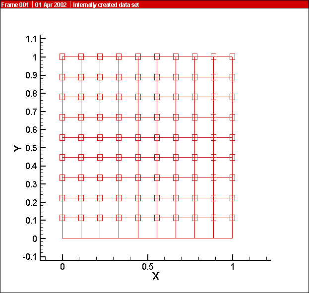 Figure 1. The effect of blanking on nodes and cells.
- Performing the Integration
-
Selecting 位于对话框底部
指定显示选项
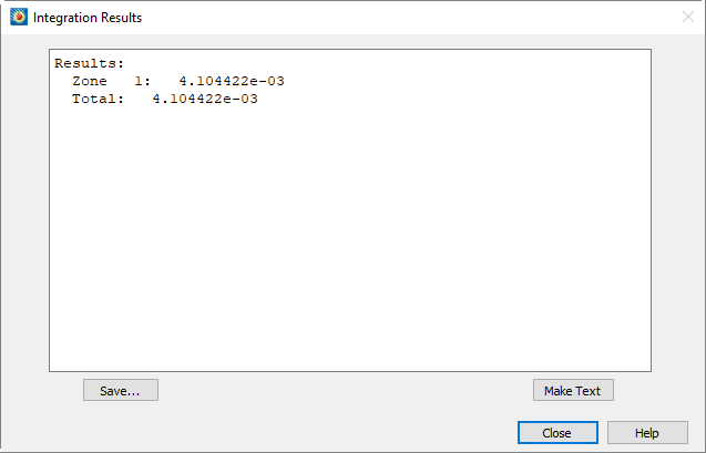
显示表格化结果
您可以在文本对话框中显示积分结果、绘制结果,或两者兼有。[T0007] 对话框底部 dialog (accessed via ) control these settings. When you have "Show Tabulated Results" toggled-on, integration results will appear in a text dialog, as shown below.
该对话框提供两个附加选项。选择[T0010] 按钮 button displays a file selection dialog which allows you to save the integration results to a text file. The [Make Text] button places a text field containing the results into the active frame. Make sure you have the frame in which you wish to place the results selected as the active frame before you select this button.
绘制结果
勾选[T0013] 复选框后 check box results in the integration results being plotted in a new frame. Each zone or time strand used in the integration results in a corresponding zone being created in this frame. For Cell integrations, the plot will not be useful, because it will contain only a single point in each zone. For plane (in 3D) or line integrations where multiple planes or lines are integrated in each zone or time strand, plotting can be very useful. In these cases, the results for each plane or line are plotted versus the corresponding index or indices.
按时间线积分时,将生成名为"Solution Time"的新变量并作为自变量绘制。共相关区域的积分结果会汇总为每个求解时间对应的单个点。若某求解时间无相关区域,则该时间步的积分值为零。
除力和力矩外,所有积分类型均可使用"Plot Results As"复选框右侧的文本字段命名结果图中用于存储积分结果的变量。对于力和力矩,九个变量名分别为Lift、Drag、Side、X-Moment、Y-Moment、Z-Moment、X-Force、Y-Force和Z-Force,初始仅显示Lift变量。
由于绘图功能会创建新帧,因此无法保存到数据日志中,且当前数据日志将失效。若后续保存布局文件,系统将提示您保存新的数据文件。
在宏中访问集成结果
宏命令可通过特定环境变量访问最近一次积分的结果。每个变量代表所有区域的总和(即[T0019] 对话框中显示的最终数值)。除力和力矩外,所有积分类型的单一结果存储在变量 dialog). For all integration types
except Forces and Moments, the single result is stored in the variable
INTEGRATION_TOTAL.
Table 1中,该表显示了力和力矩的变量名。
| 积分类型 | 环境变量 |
|---|---|
Forces and Moments |
INTEGRATION_LIFT |
所有其他类型 |
INTEGRATION_TOTAL |
环境变量在宏中的访问方式与常规宏变量相同,区别在于变量名前需添加$前缀。例如,以下宏命令将显示最近一次标量积分的结果:
$!PAUSE "Integration total = |$INTEGRATION_TOTAL|"
您也可以将积分结果作为帧辅助数据进行访问。例如,要访问INTEGRATION_TOTAL变量作为辅助数据,请使用以下语法:
INTEGRATION_TOTAL = &(AUXFRAME:CFDA.INTEGRATION_TOTAL)
集成示例
以下章节演示了 dialog.
计算曲面下的体积
Figure 2显示了一个3D曲面。我们需要计算该曲面与Z=0平面之间的体积。为此,需对曲面在Z=0平面上的投影进行Z值积分。要获取该投影,请将绘图类型切换为2D笛卡尔坐标。通过对话框(可在 menu).
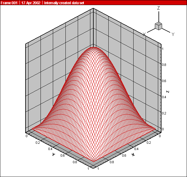
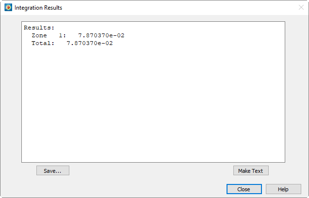
中访问),确保3D中用于X和Y的变量与2D中一致。对话框进行积分设置时,选择积分类型为Scalar,标量变量为Z。其余控件保持默认设置。点击Integrate即可显示曲面下的体积。对话框及结果如Figure 3].

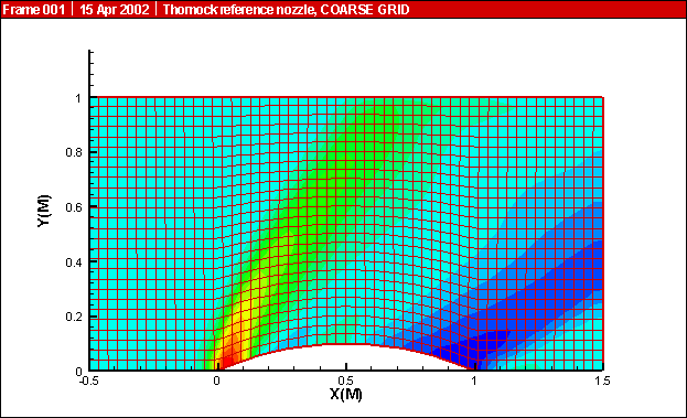
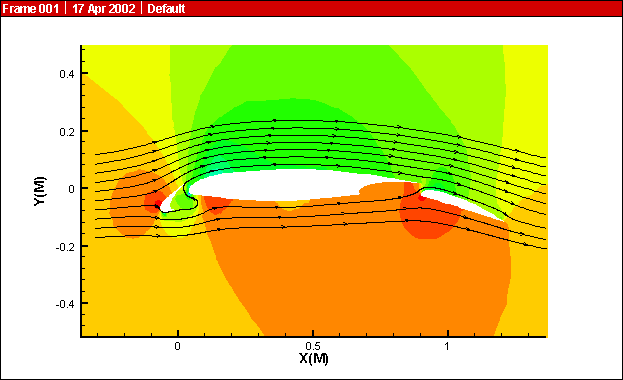
内部流动示例
接下来的几个示例将演示对话框在内部流动(如喷气发动机或管道内的流动)中的应用。我们的数据集由单个I-J有序区域组成,图中显示了网格和压力等值线。Figure 4.
计算总质量
要计算总质量,必须对密度在体积(或二维中的面积)上进行积分。如果数据集不包含密度,可通过对话框确定。(参见Calculating Variables)选择标量积分类型,将密度变量选为标量,然后对单元进行积分(对于我们的IJ有序数据,这降级为K平面)。点击积分后,总质量将作为积分结果显示出来。对话框及结果如Figure 5.
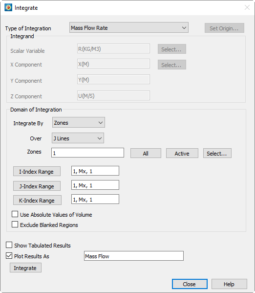
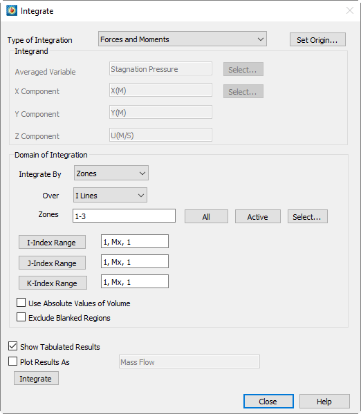
计算质量流量
| 要计算质量流量,首先必须在对话框中设置对流变量。参见Choosing the Convective Variables了解设置这些变量的信息。 |
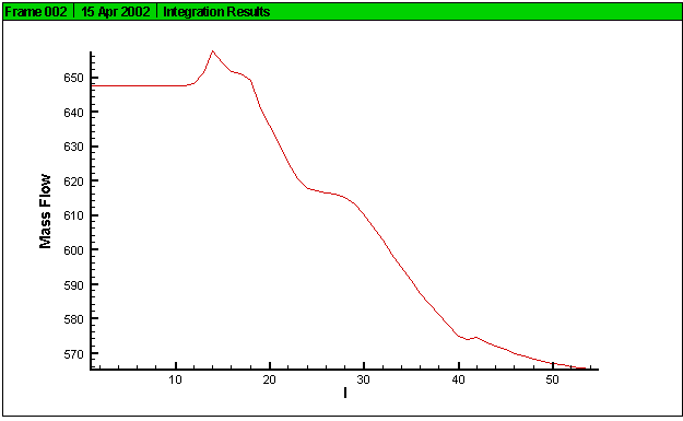
现在我们将计算流向不同位置处的质量流量。这将指示解向稳态收敛的程度。对话框通过质量流量积分类型简化了此操作。选择此选项并指定对J线(相当于二维中的I平面)进行积分。注意,对话框的整个被积函数部分被禁用。Tecplot 360根据在和 dialogs.
中输入的信息计算所需变量(动量)。我们仅希望绘制结果,因此在对话框底部选择此选项,指定结果命名为"Mass Flow"。选择积分后,质量流量将在新帧中相对于I索引绘制。对话框及绘制结果如Figure 6所示。从结果可以看出,我们的解尚未完全收敛。
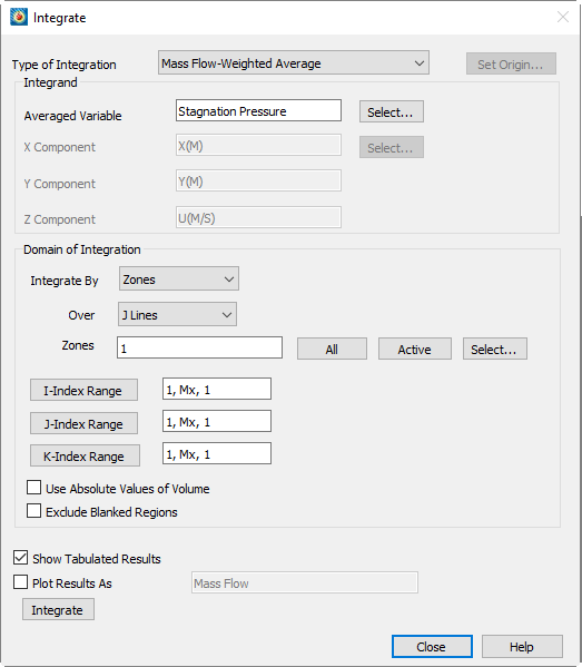
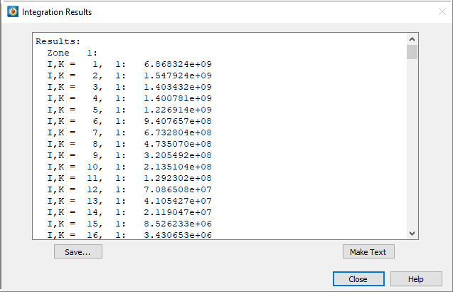
计算质量加权总压
现在我们将计算发动机分析中常用的量——质量加权滞止压力(或总压)。虽然称为"质量加权",但加权函数实际上是质量流量。因此,选择质量流量加权平均作为积分类型,从数据集中选择滞止压力变量(之前通过对话框计算)。由于我们只关心出口平面处的该值,再次选择J线(从"Integrate Over"下拉菜单),但指定I范围为(Mx, Mx, 1),仅对I=IMax平面进行积分。我们选择仅在文本对话框中显示结果。点击[Integrate]执行计算。对话框及结果如Figure 7.
计算升力和阻力
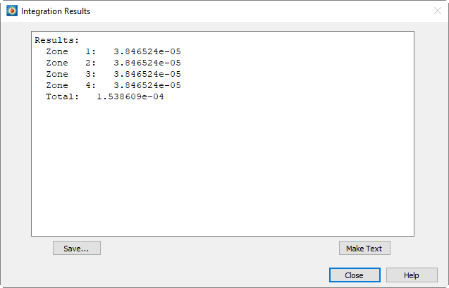
最后一个示例使用三元素翼型解,这是一个外部流动解的示例。我们的数据由四个区域组成。三个区域是IJ有序区域,捕获了每个元素周围的边界层。第四个区域是三角形有限元区域,填充了元素周围的剩余空气空间。该解的压力云图和流线如Figure 8.
所示。要计算此翼型配置的升力和阻力,我们使用力和力矩积分类型。与质量流量一样,整个被积函数部分对话框被禁用,因为 Tecplot 360 将根据其他对话框中的设置推导所需值(压力、速度梯度和粘度)。我们为三个 Edge 层区域中的每一个选择沿表面积分(J=1)线,然后点击 Integrate。[T0001] 对话框和结果如[T0002]所示。每个区域的结果分别列出。滚动到[T0003]对话框底部,我们可以看到总升力和阻力,以及其他力和力矩数据。[T0004] 指定力矩的原点[T0005] 选择积分类型后,[Set Origin] 按钮变为可用。选择此按钮将显示[T0006]对话框。在此对话框中,您可以指定计算力矩所围绕的原点的 X、Y、Z 位置。[T0007] 选择区域[T0008] 要选择区域,请在[T0009]对话框的积分域部分中选择 [All]、[Active] 或 [Select]。通过选择 [Select],您可以通过在列表中单击来选择所需的区域,或者在生成的[T0010]对话框中选择 [Zone Number] 或 [Zone Name]。选择 [Zone Number] 会调出[T0011]对话框,允许您通过数值范围指定所需的区域。选择 [Zone Name] 会提示您输入模式字符串,该字符串将与所有区域的名称进行匹配。在输入区域名称模式时,您可以使用星号作为通配符。所有名称与模式匹配的区域随后会在[T0012]中被选中。[T0013] 计算湍流函数[T0014] Tecplot 360 允许您计算并添加到数据集中的四种湍流相关量,前提是您的数据集中已有任意两个。湍流动能、耗散率、频率和运动粘度以及动态粘度可通过[T0015]获得。它包含两个下拉菜单和相关的文本字段,用于识别数据集中的两个湍流相关变量;下拉菜单用于选择要计算的函数和计算变量的位置;一个切换开关用于选择按需计算;以及一个[T0016]按钮来执行计算。[T0017] 识别湍流变量[T0018] 对话框中的前两个下拉菜单允许您指定数据集中包含哪些湍流变量。选项包括动能([T0019])、耗散率([T0020])、湍流频率([T0021])、湍流运动粘度([T0022])和湍流动态粘度([T0023])。最后一个选项是运动粘度,等于动态粘度除以密度。[T0024] 选择变量位置 dialog and results appears as in Figure 9.
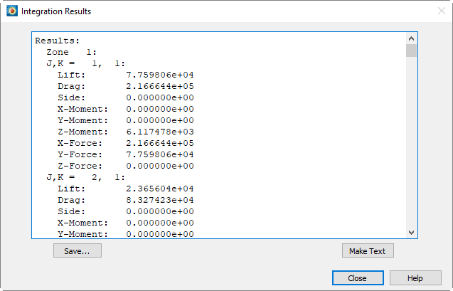
The results of each zone are listed separately. Scrolling to the bottom of the dialog, we see the total lift and drag, along with other force and moment data.
指定力矩的原点
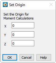
When the integration type is selected, the [Set Origin] button is active. Selecting this button displays the dialog. In this dialog, you may specify the X, Y, Z-location of the origin about which the moments will be calculated.
选择区域
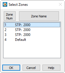
To select zones, choose [All], [Active], or [Select] from the Domain of Integration portion of the dialog. By choosing [Select], you may select the zones you want by clicking in the list, or by selecting [Zone Number] or [Zone Name] in the resultant dialog. Selecting [Zone Number] calls up the dialog, allowing you to indicate the desired zones by a numeric range. Selecting [Zone Name] prompts you for a pattern string, which is matched against the names of all zones. You may use the asterisk as a wildcard when entering the zone name pattern. All zones whose names match the pattern are then selected in the list.ht.
计算湍流函数
Tecplot 360 allows you to calculate and add to your dataset any of four turbulence-related quantities, provided you already have any given two in your dataset. Turbulent kinetic energy, dissipation rate, frequency and kinematic viscosity, and dynamic viscosity are available via the dialog.
The dialog is displayed by selecting from the menu.
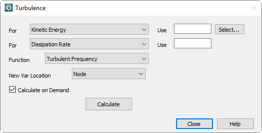
It contains two drop-down menus and associated text fields for you to identify the two turbulence-related variables in your dataset, drop-downs for you to select the function you wish to calculate and the location of the calculated variable, a toggle to select calculate-on-demand, and a button to perform the calculation.
识别湍流变量
The first two drop-down menus on the dialog allow you to specify which turbulence variables are contained in your dataset. The options are Kinetic Energy ( ), Dissipation Rate ( ), Turbulent Frequency ( ), Turbulent Kinematic Viscosity ( ), and Turbulent Dynamic Viscosity( ). This last option is the kinematic viscosity, which is equal to the dynamic viscosity divided by the density.
选择变量位置
您可以通过“新变量位置”下拉菜单选择新变量的位置(节点或单元中心),这些变量是Tecplot 360在计算过程中创建的。此设置仅影响点击“计算”时添加到数据集的新变量。数据集中已存在的变量将保留其原有位置。如需更改现有变量的位置,可删除或重命名该变量,然后使用所需的“新变量位置”设置执行计算。
按需计算
选择选项后,点击按钮时,计算变量会被添加到数据集中,但实际计算会延迟到真正需要时执行。请参考关于按需计算的讨论,详见Calculating Variables.
计算粒子路径与脉线
对于稳态解,Tecplot 360允许您通过在流场中放置流迹线来追踪无质量粒子的路径。对话框通过提供两种额外的可视化方法(粒子路径和脉线)增强了此功能,适用于有质量或无质量的粒子。
请注意,这些计算(尤其是脉线)可能需要较长时间,特别是在网格较大的情况下。
The 对话框通过选择 from the menu.
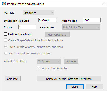
显示。其中包含一个下拉菜单,允许您选择粒子路径或脉线,以及路径积分、有质量粒子、计算粒子路径的存储与显示等相关选项。此外,脉线结果可进行动画显示。
计算粒子路径
粒子路径是单个粒子在解中经过的轨迹。在稳态流中,无质量粒子的粒子路径与脉线和流迹线相同。要计算粒子路径,您必须:
-
在希望释放粒子的位置放置流迹线,然后从对话框顶部的下拉菜单中选择“粒子路径”。(关于放置流迹线的详细信息,请参见Streamtraces).
-
指定积分时间步长。对于稳态计算,指定要执行的最大时间步数(参见Unsteady Flow以指定稳态或非稳态流动)。
-
为有质量粒子设置“粒子有质量”选项。点击“质量选项”以设置与质量相关的选项。
-
可选地,设置“从粒子路径创建单一有序区域”开关,以将所有粒子路径合并为一个IJ有序区域,而非为每条路径单独创建I有序区域。
-
选择.
指定积分时间步长与最大步数
粒子路径通过对解的速度场使用恒定时间步长进行积分计算得出,您需在"积分时间步长"文本框中输入该值。较小的步长可提高粒子路径精度,但会增加计算时间。对于非稳态计算,时间步长默认设置为解时间层级间的时间间隔。若指定的步长过大导致粒子在首个积分步长内逸出解域,系统将显示警告信息。
若已设置"流动解为稳态"选项,则必须同时指定最大积分时间步数(另请参阅Unsteady Flow).
指定质量相关选项
对于有质量粒子,请启用"粒子具有质量"选项。此操作将激活对话框中其他质量相关控件。点击"质量选项"可显示 dialog. (See Particles with Mass)。此外,您可选择存储粒子速度及其他粒子属性,或沿计算粒子路径的局部流动属性。选择"存储粒子速度、温度与质量"可沿粒子路径存储这些值;选择"存储插值解变量"则存储对应值。计算完成后,系统将告知包含这些值的数据集变量。
执行粒子路径计算
点击"计算"时,系统会在您放置的每条流线起点处生成一个粒子。若未放置任何流线,将显示错误信息。从这些起始位置开始,以首个解时间层级对应的时间(稳态计算为0)为起点,通过二阶Runge-Kutta积分对速度场推进粒子位置。对于非稳态计算,在解时间层级间执行线性插值。每个粒子的积分将持续至达到最终时间层级(非稳态计算)、完成指定时间步数(稳态计算),或粒子逸出解域。粒子路径将显示为数据集中新的I序区域,每个积分步对应新区域中的一个节点,除非您选择了"从粒子路径创建单一区域"选项(该选项将生成单一IJ序区域)。
检查粒子路径
粒子路径计算生成的每个I序区域代表一条时空轨迹。这些路径的非网格变量将包含粒子经过解域时"观测"到的解数据插值(除Specifying Mass-Related Options中讨论的情况外)。您可通过用解变量为粒子区域网格图着色来可视化此过程,具体步骤如下:
-
在绘图侧边栏中切换启用"网格"绘图层。
-
调出 dialog (accessed via the 菜单或绘图侧边栏)。
-
通过选择解区域、点击"网格显示"并选择"否"来关闭解区域的网格绘图。
-
如有必要,通过选择粒子路径区域、点击"网格显示"并选择"是"来启用其网格绘图。
-
通过选择这些区域、点击"网格颜色"并选择"多色"为粒子路径区域着色。若此前未选择等值线变量,对话框将打开供您选择。请选择用于粒子路径着色的变量。
-
若未选择"自动重绘",请点击"重绘"刷新绘图。您将看到粒子路径以等值线变量着色显示。
您可能希望启用散点图图层以查看步长大小。操作前需先关闭解区域的散点图绘制,也可通过.
计算迹线
迹线模拟涉及周期性或连续释放示踪物质(如油滴或烟雾)的实验技术。Tecplot 360通过从释放点释放一系列粒子并对非稳态速度场进行积分,计算其在最终解时刻流场中的位置。从特定释放点发射的所有粒子的最终位置构成一条迹线。计算完成后,迹线可在屏幕上或文件中进行动画显示。
计算迹线需执行以下操作:
-
识别数据集中的解时间层级。(请参阅Unsteady Flow.)
-
将迹线放置在您希望释放粒子的位置。
-
从顶部的下拉菜单中选择“Streaklines”(迹线)。 dialog.
-
输入与粒子路径计算相同的积分时间步长。(参见Specifying the Integration Time Step and Maximum Number of Steps).
-
指定粒子释放频率。(参见Specifying the Particle Release Frequency.)
-
对于有质量的粒子,启用“Particles Have Mass”(粒子有质量)选项。单击“Mass Options”(质量选项)设置质量相关选项。
-
Select .
计算稳态流动的迹线是不合理的,因为在稳态流动中,即使对于有质量的粒子,迹线与粒子路径相同(只是计算更耗时)。
指定粒子释放频率
对于迹线计算,会在整个求解时间内按序列释放粒子。每个粒子的位置使用指定的积分时间步长进行积分。粒子释放的频率由上述控件指定。按钮。在“Release”(释放)文本字段中,输入在指定时间间隔内要释放的粒子数量。在“particles per”(每...粒子)下拉菜单中,通过选择“Solution Time Level”(求解时间层)或“Unit Solution Time”(单位求解时间)来标识此时间间隔。
如果选择“Solution Time Level”(求解时间层),则会在您标识的每对求解时间层之间,按时间均匀间隔释放指定数量的粒子。如果选择“Unit Solution Time”(单位求解时间),则会在求解覆盖的时间范围内按固定间隔释放粒子。无论哪种情况,都会在求解的最终时间释放一个粒子,以便迹线包含释放点本身。更频繁地释放粒子会产生更详细的迹线(精度由积分时间步长决定),但计算时间会更长。
执行迹线计算
单击“Calculate”(计算)时,迹线会被计算并作为新的I有序区域添加到您的数据集中。要查看它们,请打开网格绘图图层,并为您的求解区域禁用网格绘图。参见Examining the Particle Paths.
对迹线进行动画处理
执行迹线计算后,动画控件对话框将被启用。迹线动画显示积分中的每个连续步骤,是可视化流动非定常性的有效方法。启用 in the 对话框以对区域和迹线一起进行动画处理。
| 请注意,后续的粒子路径或迹线计算将替换当前的迹线计算,使其无法用于动画。 |
您可以在计算迹线的帧中显示动画,或将其保存为多种格式的视频文件。要执行迹线动画,请执行以下步骤:
-
使用以下方法删除您不希望包含在动画中的任何迹线的I有序区域:.
-
从“Animate Streaklines”(迹线动画)下拉菜单中选择动画目标。
-
选择“Animate”(动画)。
-
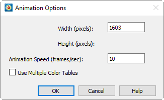
如果您选择将动画保存到文件,则Animate Options对话框将显示。输入您的动画选择并选择。然后在生成的文件选择对话框中选择文件名。
在屏幕上进行动画处理时,按钮文本将变为“取消”,允许您停止动画。当动画保存到文件时,会显示一个进度对话框,允许您取消动画。
具有质量的粒子
无质量粒子始终随局部流体速度运动,而具有质量的粒子则遵循更复杂的运动方程,其中流体对粒子产生阻力。此外,具有质量的粒子可能具有与局部流体温度不同的温度,并可能因汽化等烧蚀过程而损失质量。对话框允许您输入系数和粒子属性,以指示这些质量相关效应的计算方式。
The 对话框通过选择对话框上的Mass Options显示。它允许您指定与粒子轨迹和传热计算相关的一般或详细系数,以及重力和初始粒子速度的选项。若选择计算粒子温度,您可以选择在指定温度终止粒子,或通过详细系数选项使粒子烧蚀直至质量归零。
选择系数集
您可以输入一般系数或详细系数。一般系数是表征粒子的便捷方式,但计算精度较低。仅当粒子阻力系数和传热系数(若计算粒子温度)基本恒定时才应使用。详细系数可提高计算精度,当阻力系数或传热系数可能不恒定时(例如粒子Reynolds Number小于1000),应始终使用详细系数。此外,若要计算粒子烧蚀,必须指定详细系数。通过在 dialog.
指定重力与浮力的影响
若要在计算中考虑重力影响,请在重力场中输入数值,并选择重力作用的轴方向。
若选择详细系数集且重力非零,浮力效应也将包含在内。浮力方向与重力相反。其计算方式为:从粒子质量中减去其排开流体的质量,再将结果乘以重力常数以计算重力作用力。
若选择通用系数集,由于未指定粒子尺寸,浮力效应将不包含在内。此时重力值将直接叠加到根据通用系数和局部流动条件计算出的粒子加速度上。
通用系数
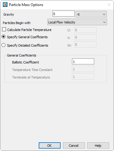
Figure 10显示对话框并展示通用系数。通用系数包含弹道系数,若需计算粒子温度,则还包括温度时间常数。
详细系数
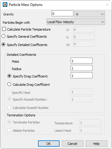
Figure 11 shows the 显示详细系数的对话框。详细系数包括粒子质量、半径和阻力系数。此外,如果正在计算粒子温度,详细系数还包括粒子比热和努塞尔数。
- 质量
-
每个粒子初始质量相同,在此文本字段中输入。如果正在计算烧蚀,粒子在流场中运动时其质量可能因烧蚀过程而减少。
- 半径
-
与质量类似,每个粒子初始半径相同,在此文本字段中输入,并可能因烧蚀而减小。
- 指定/计算阻力系数
-
您可以选择指定恒定阻力系数,或让 Tecplot 360 进行计算。若指定恒定阻力系数,请在相应文本字段中输入其值。对于计算阻力系数,Tecplot 360 使用以下公式(来自 [T0014]):Multiphase Flow and Fluidization: Continuum and Kinetic Theory Descriptions(D. Gidaspow, 1994):
其中粒子雷诺数为:
where 为粒子直径, 为粒子相对于流体的速度, 为气体的动力粘度。加速度则变为:
如果指定了非零重力,则指定方向上的加速度会加上经浮力调整的重力常数。例如,若重力常数为 [T0020],则方向变为: , acts in the direction, the acceleration in the direction becomes:
where 为粒子密度。
- 比热
-
如果正在计算粒子温度,请输入粒子的单位质量比热,单位为能量/(质量·度)。
- 指定/计算努塞尔数
-
努塞尔数是衡量传热量的无量纲参数。粒子温度变化通过该数值按以下公式计算:
where 为流体的导热系数。
若指定恒定努塞尔数,请在文本字段中输入其值。否则,Tecplot 360 将使用以下公式进行计算:An Eulerian-Lagrangian Analysis for Rocket Motor Internal Flows(Jayant S. Sabnis 等,1989):
终止选项
求解粒子温度时,您可以在粒子达到指定温度时将其终止,或计算粒子烧蚀(因释气或材料剥落导致的质量减少)。
- 终止/烧蚀粒子
-
若选择在特定温度终止粒子,则必须输入该温度值。当粒子达到此温度时,其轨迹将在该位置终止。若选择烧蚀,则需输入烧蚀起始温度及烧蚀过程的潜热。如需模拟初始固态粒子的沸腾,请将熔化潜热与汽化潜热之和作为正数输入。一旦粒子达到指定温度,后续传入粒子的热量将导致烧蚀而非进一步升温。若粒子质量降至零,其轨迹将在该位置终止。
- 温度
-
对于基于温度的终止,此为粒子被终止时的绝对温度值。对于烧蚀,此为烧蚀起始温度。
- 潜热
-
此为粒子熔化与汽化的综合潜热,仅用于粒子烧蚀计算。其单位为每单位质量能量。
分析求解误差
Tecplot 360 允许您检查网格逐次加密的CFD求解序列,估算求解精度阶数,并通过Richardson外推提高求解精度。这些功能仅适用于光滑解(无间断的解)。可通过以下方式访问: dialog.
The dialog is displayed by selecting from the menu.
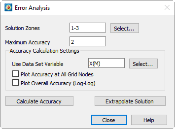
包含用于指定待分析求解区域、CFD求解器最大精度、精度计算相关选项的控制项,以及执行分析的操作按钮。
| 无法对多边形或多面体区域进行误差分析。 |
计算求解精度
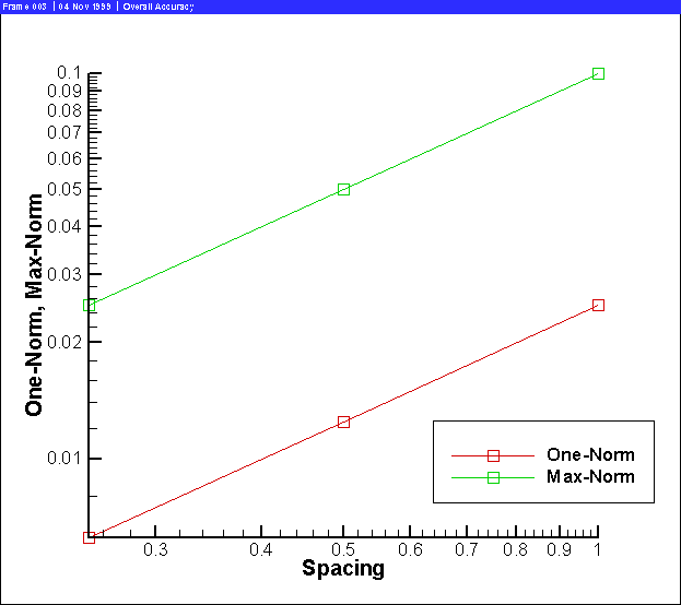
通过Richardson外推法对您选择的特定数据集变量估算三个求解序列的精度。结果将以1-范数和最大(无穷)范数形式在文本对话框中显示。您还可以选择绘制整体误差与网格间距的关系图,或绘制每个网格节点处的计算精度。
选择求解区域
要计算求解精度,必须从数据集中识别三个区域。这些区域必须代表同一问题的粗、中、细网格解。输入区域编号的顺序不影响结果。中网格在每个索引方向上的单元数必须是粗网格的两倍,或节点数加一倍。细网格的单元数必须是粗网格的四倍,或节点数加三倍。
由于有限元区域没有可识别的索引方向,粗、中、细网格尺寸的要求仅基于总单元数。假设逐次加密的网格在所有方向上均匀细化。要求中网格的单元数必须是粗网格的八倍(二维为四倍),细网格的单元数必须是粗网格的六十四倍(二维为十六倍)。
对于所有区域类型,中网格和细网格必须包含与粗网格节点重叠的节点。
您可以在文本字段中直接输入区域编号,或点击"选择"按钮并从列表中选择三个区域。
| 多边形或多面体区域类型不支持误差分析。 |
指定求解器的最大精度
在某些情况下,Richardson外推法报告的精度可能超过求解器的理论最大精度。因此,Tecplot 360将该技术使用的精度限制为您在"最大精度"文本字段中输入的值。虽然该字段允许输入小数,但您应将求解器的理论最大精度阶数输入为整数。例如,对于二阶精度求解器,应输入2。
绘制求解精度
您可以通过两种方式(可任选其一或同时使用)绘制精度计算结果。首先,通过勾选"在所有网格节点绘制精度"复选框,可在每个网格节点上以等值线图(一维数据为XY图)形式绘制精度。其次,通过勾选"绘制总体精度(对数-对数图)"复选框,可将总体误差绘制为对数-对数XY图。若选择任一选项,执行计算时系统将创建新帧来显示图形。
总体精度图绘制了三个区域中1-范数和最大(无穷)范数误差随网格间距的变化关系。该图中粗网格区域的网格间距取为1。1-范数是外推解与输入区域解之间差值的平均绝对值。最大范数是该差值的最大绝对值。Figure 12显示了该图的一个示例。两条线的斜率代表求解器的精度。斜率存在显著差异可能表明解中存在间断,或计算存在其他问题。
所有网格节点精度图基于粗网格解绘制计算得到的精度。对于二维和三维网格,以等值线图形式绘制;对于一维解,以XY图形式绘制。
由于此功能会创建新帧,因此无法保存到数据日志中,且当前数据日志将失效。若后续保存布局文件,系统将提示您保存新的数据文件。
外推解
给定三个在逐次加密网格上的解,Tecplot 360可执行Richardson外推法以提高解的精度,并报告外推解与原始细网格解之间的差异。
要执行此外推,需在对话框中按前述方法(参见Selecting Solution Zones)识别三个区域,并输入求解器的最大精度(参见Specifying the Solver’s Maximum Accuracy)。输入完成后,单击"外推解"将在解数据集中创建两个新区域。第一个新区域包含粗网格上的外推解。第二个新区域包含外推解与原始细网格解之间的差值。
提取流体流动特征
Tecplot 360可显示三维流体流动解中的重要特征,从而大大简化解的分析过程。对于跨音速流动,可显示激波面。对于所有流动(包括不可压缩流动),可显示指示涡核位置的线,以及分离线和附着线。这些计算利用了MIT的FX库。这些功能通过 dialog.
The dialog is displayed by selecting from the menu.
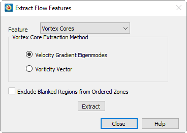
访问,其中包含用于选择所需特征的下拉菜单、指定提取涡核所用算法的选项,以及一个按钮,用于执行所需任务。
流动特征通过您在 dialog. (See Identifying Field Variables)上标识的场变量进行识别,并可能受 dialog. (See Specifying Fluid Properties)上的设置影响。特征提取也可能受边界设置影响。特别是,分离线和附着线仅在您标识为壁面边界的边界上计算。有关为数据指定边界条件的更多信息,请参阅Setting Geometry and Boundary Options。
提取激波面
要提取激波面,请从Feature下拉菜单中选择Shock Surfaces,然后点击Extract。对话框中的其余控件将被禁用。计算完成后,激波面将作为新数据集变量ShockFeature的等值面显示。该变量类似于变量,可在 dialog.
| 激波面值仅针对当前时间步计算。对于所有其他时间步,ShockFeature变量将等于零。 |
您可能会注意到,由于激波函数对解中微小振荡的敏感性,显示的激波面会被杂波遮挡。一种仅显示真实激波的有效方法是使用值消隐功能消除这些杂波出现的区域。使用Tecplot 360的对话框计算Pressure Gradient Magnitude变量,然后使用值消隐功能,在该变量小于某个常数的区域隐藏绘图。建议值为 ,对于PLOT3D无量纲数据,取0.1即可。
提取涡核
要提取涡核,请从Feature下拉菜单中选择Vortex Cores,从两种可用提取方法中选择一种,然后点击Extract。涡核由一组可能不连续的线段组成,因此使用线段有限元区域显示。显示Mesh或Edge绘图图层以查看新区域。
| 新的涡核区域是静态区域。 |
如果使用值消隐,可能需要将消隐变量插值到新区域。有关插值的信息,请参阅Data Interpolation;有关值消隐的信息,请参阅Value Blanking。
由于所用算法的特性,恰好与网格线对齐的涡旋可能无法正确提取。这在实际解中不太可能发生,但在通过拉伸二维解生成人工三维解的测试数据中较为常见。
提取分离线与附着线
分离线和附着线表示流体流动从无滑移壁面边界分离或重新附着的位置。这些线可以指示数据中分离泡或回流区域出现的位置。要计算它们,必须首先使用 dialog. (See Setting Geometry and Boundary Options识别一个或多个壁面边界。分离线和附着线将在这些边界上计算。
由于FX库用于检测分离线和附着线的算法,对于本质上是二维的流动(即沿三个空间维度之一无变化的流动),可能无法检测到这些线。
要计算分离线和附着线,请在Feature下拉菜单中选择此选项并点击Extract。这些线(如果存在)将显示在新的静态区域中,一个区域用于分离线,另一个区域用于附着线。与涡核类似,这些线由可能不连续的线段集合组成,并使用线段有限元区域显示。显示Mesh或Edge图层以查看这些线。