Conditions
This section explains the conditions related to the boundaries and the volume in a bent axis piston pump simulation.
The conditions for a desired boundary are accessed as follows:
Geometric Entities Panel > Boundaries > [Desired boundary]
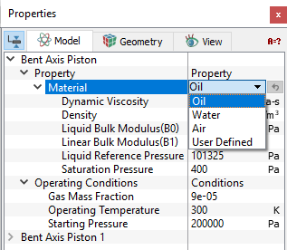
Properties Panel > Model Tab > Bent Axis Piston > [Desired options]

Figure 6.474 - Bent axis plate piston-Conditions
- Cylinder Cap: This rotates with the cylinder block but unlike the cylinder wall or piston wall, does not include any scaling (compression) or translation. This boundary condition is automatically assigned during the mesher template. The rotational attributes set under the Angular Velocity Definition are assigned to the cylinder cap.
- Cylinder Wall: This represents the surface prescribed by the projection of the piston face as it moves back and forth in the cylinder block. As such, the volume encompassed by the cylinder wall both rotates and compresses. This boundary condition is automatically assigned during the mesher template. The rotational attributes set under the Angular Velocity Definition are assigned to the cylinder wall.
- Piston Wall: This rotates and translates along with the piston as it moves back and forth in the rotating cylinder block. It corresponds to the wetted walls of the piston. This boundary condition is automatically assigned during the mesher template. The rotational attributes set under the Angular Velocity Definition are assigned to the piston wall.
Note: The rotational operating conditions specified for Cylinder Cap, Cylinder Wall and Piston Wall are set by the model template. These values cannot be changed under boundary condition options as indicated by the blue font.
- Stationary Ports: This condition facilitates the simulation of a bent axis piston in which the bent angle is controlled by sliding the cylinder block along a stationary port. When stationary port is assigned to the walls of a volume, that volume will be held stationary with respect to the drive shaft. Due to the coordinate transformation, the cylinder appears to retain its original orientation while the stationary port appears to move. It is only necessary to set a wall of the volume to be held stationary. This boundary condition cannot be used for modelling multiple bent axis pistons with shared ports. For such systems, the initial neutral position must be set-up, not as the true neutral, but at the position and angle corresponding to the desired operating angle. The Flange Axis Vector is given a value so that it is no longer aligned with the drive shaft (as for other systems), but rather with the axis of rotation of the cylinder block in the lab frame as shown below. The Cylinder Block Axis Vector is also specified in the lab frame, but as if it has been rotated past its actual operating condition.
-
Inlet: This specifies an inlet boundary for the bent axis piston pump. The Inlet boundary condition for Bent axis piston module assigns Specified Pressure Inlet as the Flow boundary condition. Additional boundary conditions for this boundary (other than the default) can be accessed using the Extended Mode.
- Outlet: This specifies an outlet boundary for the bent axis piston pump. The Outlet boundary condition for Bent axis piston module assigns Specified Pressure Outlet as the Flow boundary condition. Additional conditions for this boundary (other than the default) can be accessed using the Extended Mode.
- Rotating Wall: This specifies a rotational velocity for the surfaces which are in contact with the rotating surfaces, typically leakage gaps. This adds rotational momentum of the fluid (via the Flow module) without displacing the boundary. The reference frame used to specify the Rotational Axis Vector for a Rotating Wall is that of the Bent Axis Piston in the neutral position. For example, for a volume attached to the wall of a piston/cylinder assembly, the Rotational Axis Vector would be the same as the Flange Axis Vector. By default, this boundary condition assumes the same values of Rotational Direction, Rotational Speed (in rpm) and Rotational Axis Vector as the piston/cylinder Assembly, but these parameters can be changed.
- Wall: This corresponds to a solid boundary and by default assigns Wall for Flow and other modules. The default wall boundary assumes a stationary wall as the flow boundary condition. Additional boundary conditions for a Wall boundary (e.g. moving wall) can be accessed via the Flow module wall boundary condition using the Extended Mode.

Figure 6.475 - Stationary port |

Figure 6.476 - Shared port |
|
Note: As a parameter that defines the geometry, this boundary condition cannot be changed once a simulation has been started, even though it can be assigned. For a change in stationary port to take effect, Simerics-MP+ must be closed and restarted. |
|
The Bent Axis Piston template has following parameters that are assigned to the fluid volumes. The conditions for a desired volume are accessed as follows: Geometric Entities Panel > Volumes > [Desired Volume] Properties Panel > Model Tab > Bent Axis Piston > [Desired options] The template has extra conditions which apply to Volumes in the simulation under Bent Axis Piston module. Each volume may be assigned specific independent volume conditions.
|
Output
Primary and Derived variables can be integrated over a selected boundary and stored in the ASCII format file filename_integrals.txt for subsequent Post-Processing. These data can also be displayed real-time in the GUI using the X-Y Plots feature.
The desired output can be activated for a selected boundary in the Model Tab of the Properties Panel. The outputs which can be activated are specified as User Select (Area, Normal).
For the boundaries specified as rotor and vane, the outputs Torque, Power, Revolution Averaged Power are automatically available in the Plot Panel and displayed using X-Y Plots. For more information on outputs refer Output variables under each module.
When monitoring Points are created as part of the simulation, the output quantities are stored in the ASCII format file filename_points.txt for subsequent Post-Processing.