Material Property
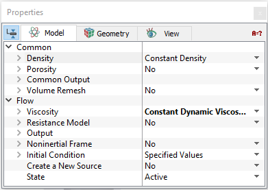
Density
|
This specifies the value of the density (kg/m3) of the material in a given volume. Density can be specified as follows:
|
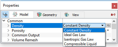
Constant Density
The value of the density of the material in a given volume is based on a user specified value.
User Defined Density
Density can be specified as a function of pressure and temperature i.e.,  using the Expression Editor under Value by selecting Constant Density.
Ideal Gas Law
The value of the density of the material in a given volume is calculated based on the Ideal Gas Law. The Ideal Gas Law requires the Minimum Pressure, Molecular Weight of the gas and the Compression Factor as input. If the Heat module is active, the Ideal Gas Law uses the computed temperature, otherwise the temperature of the gas is provided as input.
Isentropic Gas Law
The value of the density of the material in a given volume is calculated based on the Isentropic Gas Law. The Reference Pressure input is the pressure of the gas at the Reference Temperature. The value of the Adiabatic Index (Gamma) and the gas Molecular Weight are specified, to compute the density at the reference temperature. If the Heat module is active, the Isentropic Gas Law uses the computed temperature. During solution, the pressure at any given location is not permitted to drop below the designated Minimum Pressure.
Compressible Liquid
The value of the pressure dependent density of the material in a given volume is based on user specified parameters: Liquid Density at the Liquid Reference Pressure, Bulk Modulus ( ) and Linear Bulk Modulus (
 ).
).
|
Note: All the Templates model the fluid as compressible liquid. |
Viscosity
The Viscosity models (see Figure 5.18) for Newtonian and Non-Newtonian fluid is specified in Flow module as follows:
|
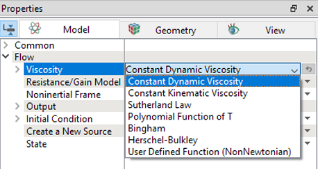
Non-Newtonian fluids
- Bingham Models: Requires specification of three parameters: Yield Stress, Critical Shear Rate and Bingham Viscosity. For more info, refer Bingham model.
- Herschel-Bulkley Model: Requires specification of four parameters: Yield Stress, Critical Shear Rate, Power Law Index and Consistency Index. For more info, refer Herschel-Bulkley model.
- User Defined: The relationship between stress and shear rate i.e.
 is specified under Stress Strain Curve using Expression Editor.
|
Note: The User Defined feature can be used to fit any arbitrary function of stress and shear rate for Non-Newtonian fluids. One example of its use would be to import experimental measurements directly as input in the form of a table, without having to resort to simplifications or curve fitting. |
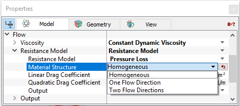
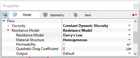
Resistance Model
The Resistance Model is used to specify a resistance for a selected volume as explained under porous media resistance models. The following two models can be specified:
|
|
|
Note: The Porosity is set in the Common module. |