中文 English
Conditions

The boundary conditions and interface conditions are automatically assigned by the Vehicle template. This section explains the conditions related to boundaries, volumes and interfaces.
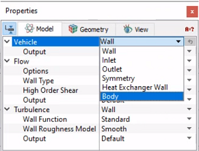
Boundary Conditions

The conditions for a desired boundary are accessed as follows:

Geometric Entities Panel > Boundaries > [Desired boundary]

Properties Panel > Model Tab >Vehicle > [Desired options]

  • Wall: This corresponds to a solid boundary and by default assigns the Wall boundary condition for Flow and other modules.
  • Inlet: This specifies an inlet boundary for the vehicle. The velocity component normal to the inlet surface is specified under Normal Inflow Velocity. The velocity is specified by the template and does not need user assignment.
  • Outlet: This specifies an outlet boundary for the vehicle. Specified Pressure Outlet is the preferred Flow boundary condition for Outlet boundary. The pressure is specified by the template and does not need user assignment.
  • Symmetry: This specifies symmetry boundary conditions.
  • Heat Exchanger Wall: This corresponds to a solid boundary and assigns Heat Exchanger Wall boundary condition for Flow and other modules in case of under hood thermal simulation. This boundary condition is automatically assigned by the template and does not need user assignment.
  • Body: This corresponds to a solid boundary, which are used for calculating the drag. Assign all the vehicle surfaces to this condition, while calculating drag coefficient.
  Note: For Flow and Turbulence related boundary conditions, refer manual.
 

Figure 7.35 - Boundary conditions


Volume Conditions

The Vehicle template has conditions which apply to Volumes in the simulation under Vehicle module. The conditions for a desired volume are accessed as follows:

Geometric Entities Panel > Volumes > [Desired Volume]

Properties Panel > Model Tab > Vehicle > [Desired options]

Each volume may be assigned specific independent volume conditions.

  • Material: The material properties are provided as a convenience and can also be set individually under the appropriate modules using Extended Mode. The default material is set to Air under Material with Constant Density.
  • Resistance Model: All heat exchanger volumes in the Geometric Entities Panel are set to Resistance Model. The Pressure Loss model is selected for Resistance Model and One Flow Direction is set as default for Material Structure. The flow direction is auto-populated. Linear and Quadratic Drag Coefficients are specified using the data from DP-V plots.

  • Operating Conditions: The operating conditions are provided as a convenience and can also be set individually under the appropriate modules using Extended Mode. The available properties depend on the modules that are active.


Figure 7.36 - Resistance model


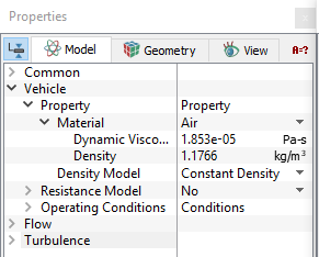
Figure 7.37 - Volume condition

  Note: Any other volume, boundary or interface condition is specified by switching from Template Mode to Advanced Mode.
Interface Conditions

This section explains the conditions related to interfaces.

The conditions for a desired interface are accessed as follows:

Geometric Entities Panel > Interface > [Desired Interface]

Properties Panel > Model Tab > Vehicle > [Desired options]

  • Vehicle: Interfaces for the Fan is automatically assigned by the template.
 

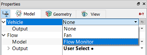
Figure 7.38 - Interface conditions
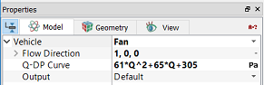
Fan

When the interface condition is selected as Fan (simulation with fan plane), the parameters can be specified as follows:

  • Flow Direction : The flow direction is set to the plane normal.
  • Q-DP curve: The expression for the pressure jump is entered directly in the box for Q-DP curve, as shown in Figure 7.39.

  •   Note: Another way of specifying pressure jump is by writing the expression inside local expression editor. Q units is in m3/s. Refer Adding Fan curve.
 

Figure 7.39 - Fan interface options

Flow Monitor

All CAD Surfaces specified as measurement surfaces in the vehicle mesher are set as Flow Monitor interfaces.


Copyright © 2023 Simerics Inc.,