Conditions
This section explains the conditions related to the boundaries and the volume in a scroll compressor simulation.
The conditions for a desired boundary are accessed as follows:
Geometric Entities Panel > Boundaries > [Desired boundary]
Properties Panel > Model Tab > Scroll > [Desired options]

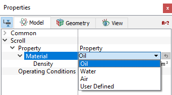
Figure 6.802 - Scroll-Conditions
- Rotor, Rotor Tip, Stator and Stator End: These boundary conditions are set automatically by the mesher template. The rotational operating conditions set under the Angular Velocity Definition are assigned to the Rotor.
- Inlet: This specifies an inlet boundary for the scroll compressor. Specified Pressure Inlet is the preferred Flow boundary condition for a scroll Inlet boundary.
- Outlet: This specifies an outlet boundary for the scroll compressor. Specified Pressure Outlet is the preferred Flow boundary condition for a scroll Outlet boundary.
- Rotating Wall: This specifies a rotational velocity for the surfaces which are in contact with the rotating surfaces, typically leakage gaps. This boundary condition assumes the same values of angular velocity and axis of rotation of the Rotor as default values, but these default values can be changed.
- Wall: This corresponds to a solid boundary and by default assigns the Wall boundary condition for Flow and other modules.
|
Note: The default values in each module under the template can be accessed and modified, by using the Extended Mode |
|
The Scroll template has the following parameters that are assigned to the fluid volumes. The conditions for a desired volume are accessed as follows: Geometric Entities Panel > Volumes > [Desired Volume] Properties Panel > Model Tab > Scroll > [Desired options] The template has additional conditions which apply to Volumes in the simulation under Scroll module. Each volume may be assigned specific independent volume conditions.
|
Output
Primary and Derived variables can be integrated over a selected boundary and stored in the ASCII format file filename_integrals.txt for subsequent Post-Processing. The quantities available for output for the boundary depend on the boundary type.
The desired output can be activated for a selected boundary in the Model Tab of the Properties Panel. The outputs which can be activated are specified as User Select (Area, Normal).
For the boundaries specified as Inlet and Outlet, the output quantities available in the Plot Panel are Revolution Average Mass Flux, Revolution Average Volume Flux .
For the boundaries specified as Rotor Tip, Rotor, Stator, Stator End, Tip Seal and Rotating Wall, the output quantity available in the Plot Panel is Revolution Averaged Power.
When monitoring Points are created as part of the simulation, the output quantities are stored in the ASCII format file filename_points.txt for subsequent Post-Processing.