|
You are here: Fluid Machinery Templates and Tutorials > External Gear Pump > External Gear Pump Model > Conditions
|
Conditions
This section explains the conditions related to boundaries and volumes in a gear pump simulation.
The conditions for a desired boundary are accessed as follows:
Geometric Entities Panel > Boundaries > [Desired boundary]
Properties Panel > Model Tab > Gear > [Desired options]
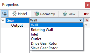
- Drive Gear Rotor: This is assigned to the drive gear boundary.
-
Slave Gear Rotor: This is assigned to the slave gear boundary.
Note: The Drive Gear Rotor boundary and Slave Gear Rotor boundary are set automatically during the Select Drive Gear operation and Select Slave Gear operation while meshing. The rotational operating conditions are set for this boundary condition using the Angular Velocity Definition which is set for the Gear template.
- Inlet: This specifies an inlet boundary for the external gear pump. Specified Pressure Inlet is the preferred Flow boundary condition for a crescent Inlet boundary.
- Outlet: This specifies an outlet boundary for the external gear pump. Specified Pressure Outlet is the preferred Flow boundary condition for a crescent Outlet boundary.
- Rotating Wall: This enables setting a rotational velocity for a boundary other than the rotor chamber, by specifying an rpm and an axis of rotation. This adds rotational sources to the momentum of the fluid (via the Flow module), it does not rotate the boundary. This boundary condition assumes the same values of angular velocity (rpm) and axis of rotation as the Drive Gear Rotor as default values, but these parameters can be changed.
- Wall: This corresponds to a solid boundary and by default assigns the Wall boundary condition for Flow and other modules.
|
Note: The default values in each module under the template can be accessed and modified, by using the Extended Mode |
|
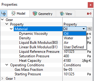
The Gear template has conditions which apply to Volumes in the simulation under Gear module. The conditions for a desired volume are accessed as follows: Geometric Entities Panel > Volumes > [Desired Volume] Properties Panel > Model Tab > Gear > [Desired options] Each volume may be assigned specific independent volume conditions.
|
Output
Primary and Derived variables can be integrated over a selected Boundary and stored in the ASCII format file filename_integrals.txt for subsequent Post-Processing. These data can also be displayed real-time in the GUI using X-Y Plots. The quantities available for output for a boundary depend on the boundary type.
The desired output can be activated for a selected boundary in the Model Tab of the Properties Panel. The outputs which can be activated are specified as User Select (Area, Normal).
For the boundaries specified as Inlet and Outlet, the output quantities available in the Plot Panel are Revolution Average Mass Flux, Revolution Average Volume Flux.
For the boundaries specified as Drive Gear Rotor, Slave Gear Rotor and Rotating Wall, the Revolution Average Power is available in the Plot Panel.
The Output Properties other than User Select, are automatically calculated and stored in the output file and may be selected and displayed in X-Y Plots.
For more information on outputs refer Output variables under each module.
When monitoring Points are created as part of the simulation, the output quantities are stored in the ASCII format file filename_points.txt for subsequent Post-Processing.