Conditions
This section explains the conditions related to the boundaries and the volumes in a radial piston simulation.
The conditions for a desired boundary are accessed as follows:
Geometric Entities Panel > Boundaries > [Desired boundary]
Properties Panel > Model Tab > Radial Piston > [Desired options]

Figure 6.369 - Radial piston-Conditions
- Cylinder Cap: This rotates with the cylinder block but unlike the Cylinder Wall or Piston Wall, does not include any scaling (compression) or translation. This boundary condition is automatically assigned during the Radial piston mesher template.
- Cylinder Wall: This represents the surface prescribed by the projection of the piston face as it moves back and forth in the cylinder block. As such, the volume encompassed by the cylinder wall both rotates and scales in volume. This boundary condition is automatically assigned during the Radial piston mesher template.
- Piston Wall: This rotates and translates along with the piston as it moves back and forth in the rotating cylinder block. It corresponds to the wetted walls of the piston. This boundary condition is automatically assigned during the Radial piston mesher template.
-
Inlet: This specifies an inlet boundary for the radial piston pump. The Inlet boundary condition for radial piston module assigns Specified Pressure Inlet as the Flow boundary condition. Additional boundary conditions for this boundary (other than the default) can be accessed using the Extended Mode.
- Outlet: This specifies an outlet boundary for the radial piston pump. The Outlet boundary condition for radial piston module assigns Specified Pressure Outlet as the Flow boundary condition. Additional conditions for this boundary (other than the default) can be accessed using the Extended Mode.
- Rotating Wall: This specifies a rotational velocity for the surfaces which are in contact with the rotating surfaces, typically leakage gaps. This adds rotational momentum of the fluid (via the Flow module) without displacing the boundary. By default, this boundary condition assumes the same values of Rotational Direction, Rotational Speed (in rpm) and Rotational Axis Vector as the piston assembly, but these parameters can be changed.
-
Wall: This corresponds to a solid boundary and by default assigns Wall for Flow and other modules. The default wall boundary assumes a stationary wall as the flow boundary condition. Additional boundary conditions for a Wall boundary (e.g. moving wall) can be accessed via the Flow module wall boundary condition using the Extended Mode.
|
Note: The Cylinder wall, Cylinder Cap and Piston Wall will be assigned the rotational attributes prescribed under the Angular Velocity Definition. As indicated by the blue font, these values cannot be changed under the Boundary Condition options. |
|
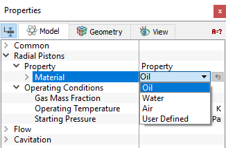
The Radial Piston template has following parameters assigned to the fluid volumes. The conditions for a desired volume are accessed as follows: Geometric Entities Panel > Volumes > [Desired Volume] Properties Panel > Model Tab > Radial Piston > [Desired options] The template has extra conditions which apply to Volumes in the simulation under Radial Piston module. Each volume may be assigned specific independent volume conditions.
|
Outputs
Primary and Derived variables can be integrated over a selected boundary and stored in the ASCII format file filename_integrals.txt for subsequent Post-Processing. These data can also be displayed real-time in the GUI using the X-Y Plots feature.
The desired output can be activated for a selected boundary in the Model Tab of the Properties Panel. The outputs which can be activated are specified as User Select (Area, Normal).
For the boundaries specified as rotor and vane, the outputs Torque, Power, Revolution Averaged Power are automatically available in the Plot Panel and displayed using X-Y Plots. For more information on outputs refer Output variables under each module.
When monitoring Points are created as part of the simulation, the output quantities are stored in the ASCII format file filename_points.txt for subsequent post-processing.