3.2 Geometric Entities Panel
|
The Geometric Entities Panel provides access to geometry related entities.
They are explained as follows: |
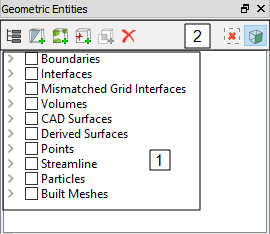
Figure 3.10 - Geometric entities panel |
|
Note: Only the selection of the entities is made in the Geometric Entities Panel. The corresponding operations and the settings are specified using a combination of the other panels. For example, if a volume or boundary is selected in the Geometric Entities Panel, it can be split, combined or rotated using the Mesh Panel, while the properties and conditions are specified in the Properties Panel. |
3.2.1 Geometric Entities
The geometric entities in the Geometric Entities Panel are the Volumes, Boundaries, Interfaces, CAD Surfaces, Derived Surfaces, Points, Streamline, Particles and Built Meshes.

Figure 3.11 - Geometric entities
CAD Surfaces
Surfaces is a term used in Simerics-MP/Simerics-MP+ to refer to a collection of points and lines (triangulation) that define a surface. These are used to define the geometry for a simulation and are used to generate the numerical mesh. Geometry refers to surfaces that define two-dimensional or three-dimensional objects. Once geometry is imported into Simerics-MP/Simerics-MP+, the surfaces defining a geometry are listed under CAD Surfaces.
- CAD Surfaces are different from Boundaries or Interfaces in that they are not connected to the mesh and are not part of the solution. They are typically used to define the shape of a volume during mesh creation.
- CAD Surfaces are typically in .STL format, but can be in other formats as well, including Nastran Grid Format, Gambit Neutral Format or ANSYS CDB file.
Volumes
Mesh (or Grid) in Simerics-MP refers to a collection of points and lines that define the Volumes (2D or 3D) and Boundaries used by the numerical solver. The mesh in Simerics-MP/Simerics-MP+, is unstructured and is generated from CAD Surfaces. The Grid is both on the boundaries of a volume and on the interior. The Grid is stored in a Simerics proprietary file format with the file extension *.sgrd.
Volumes are created:
- During mesh generation, if a closed (“water-tight”) collection of CAD Surfaces is selected.
Boundaries
A boundary is a collection of mesh cell faces that defines an external surface boundary of a model. “External” does not necessarily mean that the boundary is at the exterior of the model, but rather that is not numerically connected to any mesh cells on the other side. Boundary information is used directly in the numerical simulation.
Boundaries are created/introduced by one of two ways:
- During mesh generation, if they correspond to an external boundary in the CAD Surfaces.
- Interfaces between two Volumes are automatically converted to Boundaries if one of the Volumes is deleted.
Interface
This is an internal boundary within a model. It can reside within a volume or connect two separate volumes. It connects the mesh cells on either side of the interface. For more information, refer Interface Creation.
Mismatched Grid Interface(MGI)
Mismatched Grid Interfaces (MGI) is an algorithm for connecting boundaries. For more information, refer Interface Creation.
Built Meshes
When meshes are created using either the General Mesher or the Template Mesh/Surface, a new entity appears in the Geometric Entities Panel under Built Meshes.
They provide a list of the meshes generated and contains the relevant information pertaining to the created mesh construction.
- The CAD Surfaces used to make a water-tight, completely closed volume.
- The mesh settings used when the mesh was generated (cell size, cell size on particular surfaces, etc.).
- This also gives the choice to regenerate the mesh (Finer or Coarser, clustering in a particular area, etc.).
Derived Surfaces
These are geometric entities created explicitly, typically for post processing.
- Two derived entities, Iso-surfaces and Sections, can be created using Create an Isosurface and Create a Cross-Section, respectively.
- Once created, they are listed in the Geometric Entities Panel under the heading Derived Surfaces.
- For more information, click Create an Isosurface and Create a Cross-Section.
Points
Points are specified  coordinates within a model, used to record data of Primary Variables, Physical Properties, and Derived Variables at that location. Points are created using the Create a Monitoring Point
 ![]() icon in the Geometric Entities Panel.
icon in the Geometric Entities Panel.
Streamline
Streamline module is used to create Streamline in the flow. For information on the creation and display of Streamline, see Streamline module.
Particles
Particle module is used to create particles. For information on the creation and display of particles, see Particle module.
|
Note: The Boundaries, Interfaces, Volumes are listed as an independent category or as a sub-category, subordinate to their respective Volumes using the Group Entities by Volumes/Types |
3.2.2 Geometric Functions
The geometric functions in the Geometric Entities Panel allow to create Cross Section, Points, Isosurface, Connect Boundaries via MGI, Delete selected entity etc.
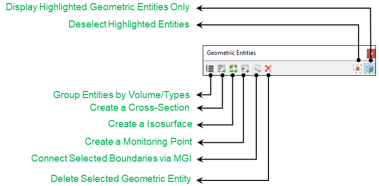
Figure 3.12 - Geometric functions
Group Entities by Volume/Types  /
/ 
This switches between the listing of geometric entities: either as independent categories based on type or as a hierarchy based on volumes. See Figure 3.13 and Figure 3.14.
|
|
|


Create a Cross-Section

This is used to create cross-sections. The orientation of the cross-section is set in the Properties Panel corresponding to an ordinate direction (Plane X, Plane Y, or Plane Z) or an angle (Arbitrary Plane).
Create a Isosurface

This is used to create iso-surfaces. The shape of a given Iso-surface depends on the Isosurface Variable, Display Option and Value as set in the Properties Panel.
Create a Monitoring Point 
A point is a specified  coordinate within a model, used to record Primary Variables, Physical Properties and Derived Variables data at that location. For more information, go to Points.
Connect Selected Boundaries via MGI 
Boundaries are connected using Connect Selected Boundaries via MGI option in the Geometric Entities Panel. MGI is an algorithm for connecting boundaries. For more information, go to Connect Selected Boundaries via MGI.
Delete Selected Geometric Entity
- This permanently removes a selected item.
- There is no “undo” for deletion.
- If an entity is associated with another entity, the sub-ordinate entity must be deleted first. For example, MGIs connected to a volume must be deleted prior to deleting the Volume.
Deselect Highlighted Entities 
This turns off the display of the selected entity and reverts to the display of all entities.
Display Highlighted Geometric Entities 
This toggles between the display of the selected entities versus display of all entities.